A step-by-step photo log of the process to add VPro graphics to an Origin 350 follow the hinv related posts.
Code:
hinv -vm
Location: /hw/module/001c01/node
IP53_2CPU Board: barcode NKW201 part 030-1863-001 rev -D
Location: /hw/module/001c01/IXbrick/xtalk/12
ASTODY Board: barcode MLV203 part 030-1726-003 rev -E
Location: /hw/module/001c01/IXbrick/xtalk/15
2U_INT_53 Board: barcode NME262 part 030-1809-006 rev -B
Location: /hw/module/001c01/IXbrick/xtalk/15/pci-x/0/1/ioc4
IO9 Board: barcode NLC357 part 030-1771-005 rev -A
2 600 MHZ IP35 Processors
CPU: MIPS R16000 Processor Chip Revision: 2.1
FPU: MIPS R16010 Floating Point Chip Revision: 2.1
CPU 0 at Module 001c01/Slot 0/Slice A: 600 Mhz MIPS R16000 Processor Chip (enabled)
Processor revision: 2.1. Scache: Size 4 MB Speed 300 Mhz Tap 0xc
CPU 1 at Module 001c01/Slot 0/Slice C: 600 Mhz MIPS R16000 Processor Chip (enabled)
Processor revision: 2.1. Scache: Size 4 MB Speed 300 Mhz Tap 0xc
Main memory size: 6144 Mbytes
Instruction cache size: 32 Kbytes
Data cache size: 32 Kbytes
Secondary unified instruction/data cache size: 4 Mbytes
Memory at Module 001c01/Slot 0: 6144 MB (enabled)
Bank 0 contains 1024 MB (Premium) DIMMS (enabled)
Bank 1 contains 1024 MB (Premium) DIMMS (enabled)
Bank 2 contains 1024 MB (Premium) DIMMS (enabled)
Bank 3 contains 1024 MB (Premium) DIMMS (enabled)
Bank 4 contains 512 MB (Premium) DIMMS (enabled)
Bank 5 contains 512 MB (Premium) DIMMS (enabled)
Bank 6 contains 512 MB (Premium) DIMMS (enabled)
Bank 7 contains 512 MB (Premium) DIMMS (enabled)
Integral SCSI controller 2: Version IDE (ATA/ATAPI) IOC4
CDROM: unit 0 on SCSI controller 2
Integral SCSI controller 3: Version SAS/SATA LS1068
Integral SCSI controller 0: Version QL12160, low voltage differential
Disk drive: unit 1 on SCSI controller 0 (unit 1)
Disk drive: unit 2 on SCSI controller 0 (unit 2)
Integral SCSI controller 1: Version QL12160, low voltage differential
IOC3/IOC4 serial port: tty3
IOC3/IOC4 serial port: tty4
IOC3/IOC4 serial port: tty5
IOC3/IOC4 serial port: tty6
Graphics board: V12
Integral Gigabit Ethernet: tg0, module 001c01, PCI bus 1 slot 4
Iris Audio Processor: version MAD revision 1, number 1
PCI Adapter ID (vendor 0x10a9, device 0x100a) PCI slot 1
PCI Adapter ID (vendor 0x1000, device 0x0054) PCI slot 2
PCI Adapter ID (vendor 0x1077, device 0x1216) PCI slot 3
PCI Adapter ID (vendor 0x14e4, device 0x1645) PCI slot 4
PCI Adapter ID (vendor 0x1412, device 0x1724) PCI slot 1
PCI Adapter ID (vendor 0x1033, device 0x0035) PCI slot 2
PCI Adapter ID (vendor 0x1033, device 0x0035) PCI slot 2
PCI Adapter ID (vendor 0x1033, device 0x00e0) PCI slot 2
IOC4 firmware revision 83
IOC3/IOC4 external interrupts: 1
HUB in Module 001c01/Slot 0: Revision 2 Speed 200.00 Mhz (enabled)
IP35prom in Module 001c01/Slot n0: Revision 6.210
USB controller: type OHCI
USB controller: type OHCI
Graphics via
a Fuel V12 inserted in the O350's XIO slot.
Code:
/usr/gfx/gfxinfo -v
Graphics board 0 is "ODYSSEY" graphics.
Managed (":0.0") 1280x1024
BUZZ version B.1
PB&J version 1
128MB memory
Banks: 4, CAS latency: 3
Monitor 0 type: NEC 26089
Input Sync: Voltage - Video Level; Source - Internal; Genlocked - False
Channel 0:
Origin = (0,0)
Video Output: 1280 pixels, 1024 lines, 60.00Hz (1280x1024_60)
Video Format Flags: (none)
Sync Disabled
Using Gamma Map 0
Code:
scsicontrol -i /dev/scsi/sc*
/dev/scsi/sc0d1l0: Disk SEAGATE ST336753LC 0005
ANSI vers 3, ISO ver: 0, ECMA ver: 0; supports: 16bit synch linkedcmds cmdqueing
Device is ready
/dev/scsi/sc0d2l0: Disk SEAGATE ST336753LC 0005
ANSI vers 3, ISO ver: 0, ECMA ver: 0; supports: 16bit synch linkedcmds cmdqueing
Device is ready
/dev/scsi/sc2d0l0: CD-ROM MATSHITADVD-ROM SR-8178 PZ21
ANSI vers 0, ISO ver: 0, ECMA ver: 0; supports:
Device is not ready
As bri3d noticed
, the insertion of graphics changed the L1 brick identity from Chimera Server to Chimera Blade:
Code:
ack: 001, slot: 01, partition: none, type: Chimera Blade [2MB flash], serial:NME262, source: EEPROM
L1 Controller Environmental monitoring with V12 installed and several hours run time.
Code:
l1cmd env
Environmental monitoring is enabled and running.
Description State Warning Limits Fault Limits Current
-------------- ---------- ----------------- ----------------- -------
1.8V Enabled 10% 1.62/ 1.98 20% 1.44/ 2.16 1.777
12V <not present>
12V #2 Enabled 10% 10.80/ 13.20 20% 9.60/ 14.40 12.000
3.3V Enabled 10% 2.97/ 3.63 20% 2.64/ 3.96 3.320
12V IO Enabled 10% 10.80/ 13.20 20% 9.60/ 14.40 12.000
5V AUX Enabled 10% 4.50/ 5.50 20% 4.00/ 6.00 5.044
3.3V AUX Enabled 10% 2.97/ 3.63 20% 2.64/ 3.96 3.268
PCI 5V AUX Enabled 10% 4.50/ 5.50 20% 4.00/ 6.00 5.044
PCI 3.3V Enabled 10% 2.97/ 3.63 20% 2.64/ 3.96 3.302
PCI 2.5V Enabled 10% 2.25/ 2.75 20% 2.00/ 3.00 2.496
PCI 5V Enabled 10% 4.50/ 5.50 20% 4.00/ 6.00 4.940
XIO 12V BIAS Enabled 10% 10.80/ 13.20 20% 9.60/ 14.40 12.000
XIO 5V Enabled 10% 4.50/ 5.50 20% 4.00/ 6.00 4.940
XIO 2.5V Enabled 10% 2.25/ 2.75 20% 2.00/ 3.00 2.457
XIO 3.3V AUX Enabled 10% 2.97/ 3.63 20% 2.64/ 3.96 3.285
IP53 3.3V AUX Enabled 10% 2.97/ 3.63 20% 2.64/ 3.96 3.251
IP53 5V AUX Enabled 10% 4.50/ 5.50 20% 4.00/ 6.00 5.044
IP53 12V Enabled 10% 10.80/ 13.20 20% 9.60/ 14.40 12.000
IP53 VCPU Enabled 10% 1.13/ 1.38 20% 1.00/ 1.50 1.269
IP53 SRAM Enabled 10% 2.25/ 2.75 20% 2.00/ 3.00 2.483
IP53 1.5V Enabled 10% 1.35/ 1.65 20% 1.20/ 1.80 1.480
Description State Warning RPM Current RPM
--------------- ---------- ----------- -----------
FAN 0 EXHST 1 Enabled 1980 2177
FAN 1 PS Enabled 3200 4066
FAN 2 PCI 1 Enabled 1980 2343
FAN 3 PCI 2 Enabled 1980 2576
FAN 4 ODY Enabled 1679 4272
Advisory Critical Fault Current
Description State Temp Temp Temp Temp
----------------- ---------- --------- --------- --------- ---------
0 INTERFACE 0 Enabled [Autofan Control] 75C/167F 44C/111F
1 INTERFACE 1 Enabled [Autofan Control] 75C/167F 43C/109F
2 INTERFACE 2 Enabled [Autofan Control] 75C/167F 35C/ 95F
3 PCI RISER Enabled [Autofan Control] 75C/167F 34C/ 93F
4 ODYSSEY Enabled [Autofan Control] 75C/167F 35C/ 95F
5 NODE Enabled [Autofan Control] 75C/167F 33C/ 91F
6 BEDROCK Enabled [Autofan Control] 75C/167F 48C/118F
Zone Temp Target Current Zone Fan Curr/Min
Zone Name State Sensors Average Average Index Fan %
--------- -------- ------------ -------- -------- --------- ---------
NODE Enabled 0,1,2,5,6 47C/116F 40C/104F 0 18%/ 18%
PS Enabled 0,1,2,5,6 47C/116F 40C/104F 1 55%/ 55%
PCI Enabled 3 45C/113F 34C/ 93F 2,3 55%/ 55%
ODY Enabled 4 48C/118F 35C/ 95F 4 55%/ 55%
L1 "serial all" command:
Code:
l1cmd serial all
Data Location Value
------------------------------ ------------ --------
Local System Serial Number NVRAM M2008383
Reference System Serial Number NVRAM M2008383
Local Brick Serial Number EEPROM NME262
Reference Brick Serial Number NVRAM NME262
EEPROM Product Name Serial Part Number Rev T/W
---------- -------------- ------------- -------------------- --- ------
INTERFACE 2U_INT_53 NNX272 030_1809_006 B 00
IO9 IO9 NLC357 030_1771_005 A 00
ODYSSEY ASTODY MLV203 030_1726_003 E 00
RISER 2U_RISER NND054 030_1808_006 B 00
NODE IP53_2CPU NKW201 030_1863_001 D 00
SNOWBALL no hardware detected
PS 1 no hardware detected
PS 2 DPS-500EBE XPD0451009596 060-0178-003 S4
EEPROM JEDEC-SPD Info Part Number Rev Speed SGI
---------- ------------------------ ------------------ ---- ------ --------
DIMM 0 CE000000000000000C6F6F00 M3 46L2820BT2-CA0 2B 10.0 N/A
DIMM 2 CE000000000000000C576F00 M3 46L2820BT2-CA0 2B 10.0 N/A
DIMM 4 CE000000000000000CEF8300 M3 46L6423DT3-CA0 3D 10.0 N/A
DIMM 6 CE000000000000000CC18400 M3 46L6423DT3-CA0 3D 10.0 N/A
DIMM 1 CE000000000000000CBD6F00 M3 46L2820BT2-CA0 2B 10.0 N/A
DIMM 3 CE000000000000000C786F00 M3 46L2820BT2-CA0 2B 10.0 N/A
DIMM 5 CE000000000000000C0E8400 M3 46L6423DT3-CA0 3D 10.0 N/A
DIMM 7 CE000000000000000CF48300 M3 46L6423DT3-CA0 3D 10.0 N/A
The conversion from Origin 350 to Onyx 350 took less than two hours, including trimming the V12 bulkhead and heatsink.
Attachment:
File comment:
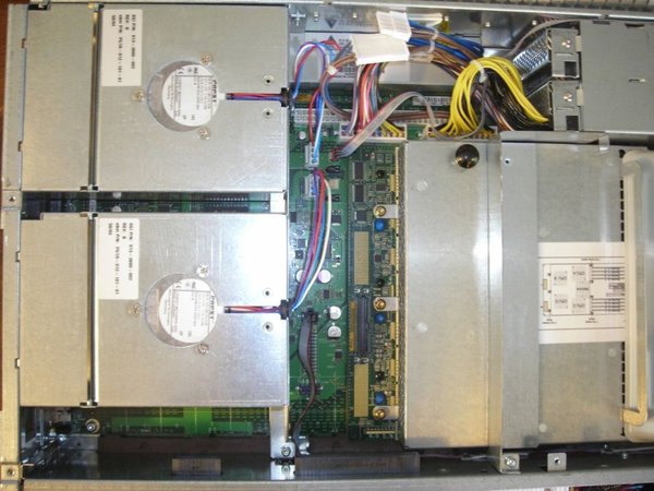
Unmodified Origin 350 - a Fuel VPro graphics board will replace the lower exhaust fan.
 Before.jpg [ 112.29 KiB | Viewed 483 times ]
Attachment:
File comment:
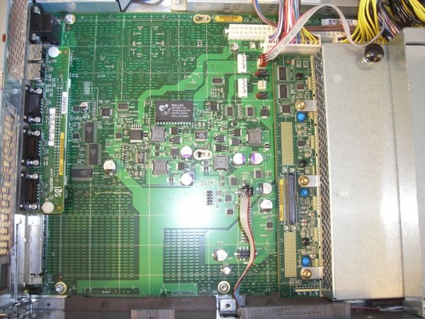
Both exhaust fans and support bracket removed. Required removal of only 8 screws, 3 in each fan and 2 for the support bracket (one of the support bracket screws is accessed from the exterior).
 During.jpg [ 166.08 KiB | Viewed 483 times ]
Attachment:
File comment:
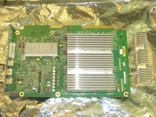
Fuel VPro Graphics board - the bulkhead and heatsink have been trimmed to fit the Origin 350.
 Modified_V10.jpg [ 148.91 KiB | Viewed 345 times ]
Attachment:
File comment:
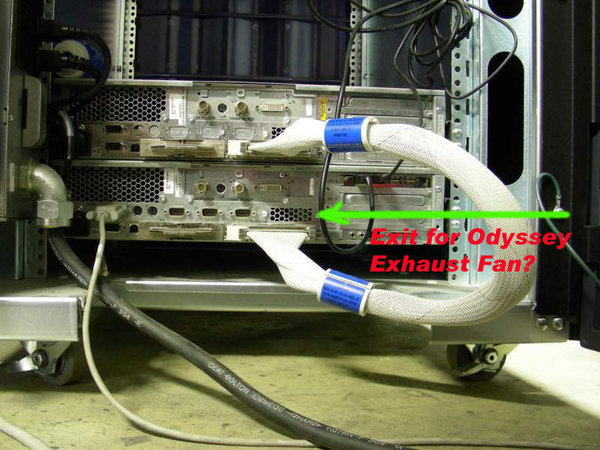
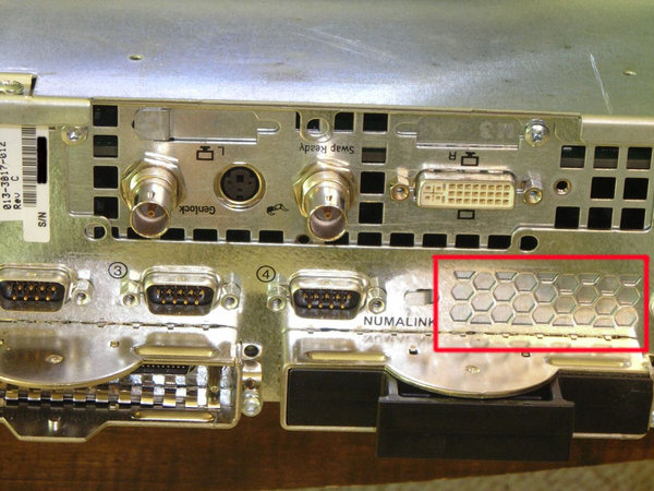
There is an opening on the rear of the case just below the position of the installed graphics board. The opening has a cover plate on headless Origin 350s. The cover can be removed and a radial fan installed internally to provide extra cooling.
The openings seen in the graphics board bulkhead should be sealed so the fans will draw cool air through the nodeboard shroud and across the graphics board heatsink, rather than through the opens in the graphics board bulkhead and right back out via the fans.
 Fan_Exhaust_Port.jpg [ 180.22 KiB | Viewed 341 times ]
Attachment:
File comment:
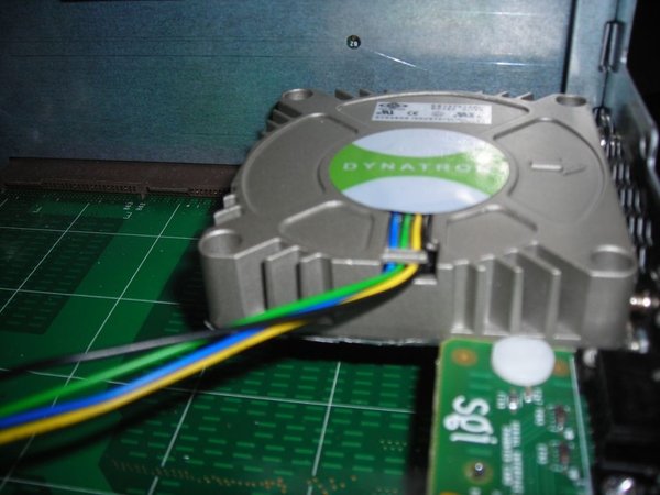
70mm radial fan (this one is rated at 14.7CFM). The 70mm fan is a tight fit between the PCI riser and the IO9 daughter card. The fan is positioned to exhaust air through an exhaust grill (the grill has a removable cover plate). This photo was taken during a 'test' fit; before final installation a gasket was added to seal the gap between the fan and the case.
This particular fan was used because it was what the local computer parts place had in stock that was the right size. It's a Dynatron 70mm Radial fan, most commonly used on low-profile CPU coolers (for 1U servers). It might be possible to fit larger radial fan if the exhaust ducting is arranged to place the body of the fan behind the IO9 daughter board (seen in the right foreground of the photo).
 Fan - side view.jpg [ 82.31 KiB | Viewed 341 times ]
Attachment:
File comment:
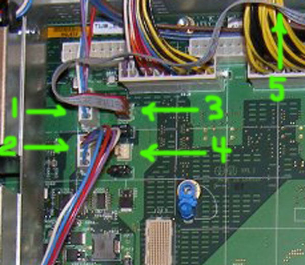
Three-pin header for graphics fan. To avoid L1 "Fan Error" messages, a 3-pin fan that proves fan speed information must be used. The header uses a non-standard pinout: Pin 1 - 12VDC; Pin 2 - Tach; Pin 3 - Ground. NOTE: A 4-pin PWM fan may also be used; the O350 fan header and the PWM fan socket are keyed to allow connection of only the 3 necessary fan wires (although the 12VDC, tach and ground wires should be configured to match the SGI pinout).
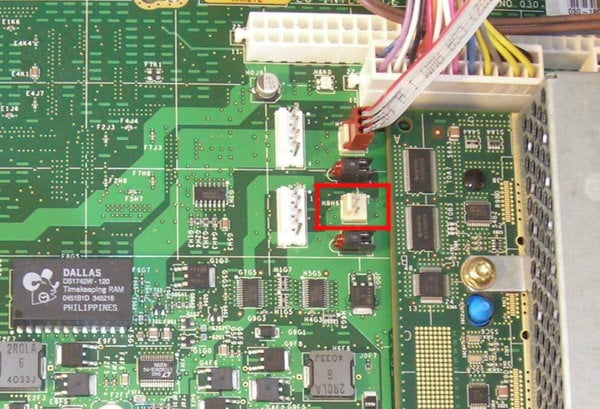 graphics_fan_header.jpg [ 190.09 KiB | Viewed 341 times ]
Attachment:
File comment:
Upper exhaust fan replaced (without bracket) and a VPro graphics board installed in place of lower fan (the heatsink and bulkhead on the graphics board must be trimmed to allow installation). The large square metal object visible in the graphics board is the backing plate/attachment mechanism for the VPro heatsink. There is a threaded hole in the center of this assembly that will align with an opening in the lid of the O350 - inserting a screw through the O350 lid into the threaded hole will provide support to the graphics board.
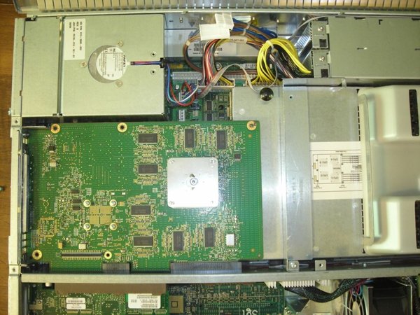 After.jpg [ 143.86 KiB | Viewed 483 times ]
Attachment:
File comment:
PROM boot screen after installation of a VPro graphics board from a Fuel (the monitor is a 1600SW).
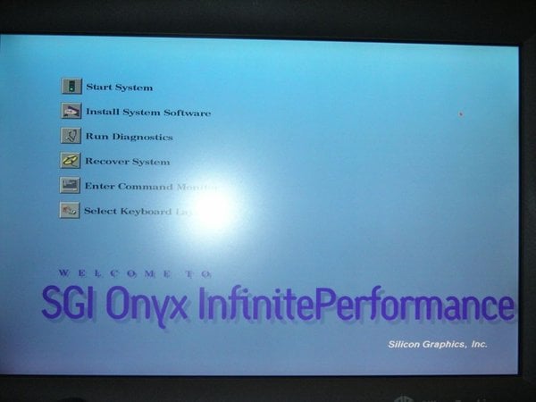 Results.jpg [ 57.96 KiB | Viewed 483 times ]
Attachment:
File comment:
Unused Origin 350 exhaust fan and bracket; and sections trimmed from the graphics board bulkhead / heatsink.
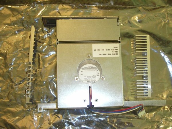 Leftover.jpg [ 120.14 KiB | Viewed 483 times ]


