SGI: Hardware

Fuel PSU problems - Page 3

Cool. This could mean that, with some proper reverse-engineering and a copy of the board, we could try to "SGI-alize" that Intel-spec PSU.

If that's successful there's that obvious step forward and go try the same "extra circuit board" trick on other power supply, ofcourse depending how deeply involved this little extra circuit board might be to the rest of the Sparkle PSU design.

To carry on dreaming - is this thing even bound to be inside the PSU? Can it be tricked to stay between PSU and motherboard connector?
Imagine a piggyback configuration made up of a short PSU extension connector cable and use regular ATX power supply. Fuel believe PSU fan is doing alright, while the PSU has its own fan environmental controlling. Oh, the possibilities... (Or maybe I'm on a crackpipe this morning)
:O3200: :Fuel: :Indy: :O3x02L:
@Recondas: good work!

ramq wrote: Cool. This could mean that, with some proper reverse-engineering and a copy of the board, we could try to "SGI-alize" that Intel-spec PSU

Only if your aim is not to increase the world wide supply of 'SGI-spec' PSU's.

If you're just looking for a way to get a dead Fuel going again, transplanting that little PCB from a dead SGI-spec to the vanilla Intel-spec PSU is probably what you want to do, and doesn't require any reverse engineering :)
Now this is a deep dark secret, so everybody keep it quiet :)
It turns out that when reset, the WD33C93 defaults to a SCSI ID of 0, and it was simpler to leave it that way... -- Dave Olson, in comp.sys.sgi

Currently in commercial service: Image :Onyx2: (2x) :O3x02L:
In the museum : almost every MIPS/IRIX system.
Wanted : GM1 board for Professional Series GT graphics (030-0076-003, 030-0076-004)
@recondas, if you are willing to do a bit more disassembly, could you take an extra pic of that SGI specific board?
Google: Don't Be Evil. Apple: Don't Be Greedy. Microsoft: Don't Be Stupid.
guardian452 wrote: @recondas, if you are willing to do a bit more disassembly, could you take an extra pic of that SGI specific board?
That was my original intention, but even with the attachment screw removed there's too little play in the wiring to turn the board far enough to get a shot of the surface components - didn't want to risk breaking a solder connection and fubar a working PS.
***********************************************************************
Welcome to ARMLand - 0/0x0d00
running...(sherwood-root 0607201829)
* InfiniteReality/Reality Software, IRIX 6.5 Release *
***********************************************************************
Alright, well I was just curious :)
Google: Don't Be Evil. Apple: Don't Be Greedy. Microsoft: Don't Be Stupid.
So I decided to pursue the ATX->Fuel conversion as well, with priceless of Pontus' and Recondas' research and diagrams, I can report success.
Oh, did I mention I met with Hamei 2 weeks ago for dinner and beers, he gave me his spare Fuel M/B - proved extremely useful for testing my ATX conversion :)

I got this:

Image

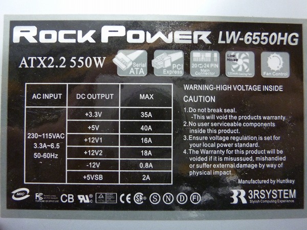
RockPower 550W PSU, ATX2.2, model LW-6550HG (used for ~11$), and another AQTIS 600W AP-600GR (about the same price)
I decided to use the RP - since its power levels are much closer to my Fuel's NMB (lacks a little on the 3V3 and 5Vsb).
(NMB supplies: 27A on 5V, 16A on 12VIO, 18A on 12Vdig, 45A on 3.3V, 3A on 5Vsb, and 0.6A on -12V)

The PSU has 20+4 separable connector, 4-PIN 12V (P4 connector?), couple of HDD Molex, FDD, SATA, and 2x PCI-express.

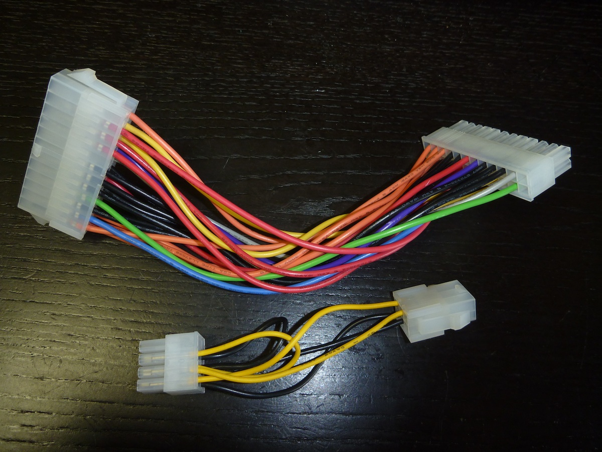
I also bought a few ATX 24-24 extenders, one ATX 24->20 and 20-24, and a few ATX 24 plugs/sockets with pins.
(hint - removing pins without real pin extractor (20$) takes a little practice, I found a sewing needle held tighly in the pliers to work well - wiggle here and there and it works)

Following my own research (looking at pins on the NMB), Recondas' diagram and Pontus' post as well - I've built conversion-extender for ATX.
Started with connecting all the GND pins, and 5VSB, checked L1 - it worked from the start.

As expected, only 5VSB and 3V3SB are available - since I connected only 5V, it means the MB is converting 5V to 3.3 (probably to power up all the env monitoring chips etc).

Code: Select all

Connected.
ALERT: Unknown PSC: 15
INFO: Cannot disable power supply: 17


SGI SN1 L1 Controller
Firmware Image B: Rev. 1.10.12, Built 02/01/2002 14:40:22


001a01-L1>
001a01-L1>env
Environmental monitoring is enabled and running.

Description    State       Warning Limits     Fault Limits       Current
-------------- ----------  -----------------  -----------------  -------
12V   Wait Pwr  10%  10.80/ 13.20  20%   9.60/ 14.40    0.13
12V IO   Wait Pwr  10%  10.80/ 13.20  20%   9.60/ 14.40    0.13
5V   Wait Pwr  10%   4.50/  5.50  20%   4.00/  6.00    0.00
3.3V   Wait Pwr  10%   2.97/  3.63  20%   2.64/  3.96    0.29
2.5V   Wait Pwr  10%   2.25/  2.75  20%   2.00/  3.00    0.00
1.5V   Wait Pwr  10%   1.35/  1.65  20%   1.20/  1.80    0.00
5V aux   Wait Pwr  10%   4.50/  5.50  20%   4.00/  6.00    5.10
3.3V aux   Wait Pwr  10%   2.97/  3.63  20%   2.64/  3.96    3.29
PIMM0 12V bias   Disabled  10%  10.80/ 13.20  20%   9.60/ 14.40    0.00
Asterix SRAM   Wait Pwr  10%   2.25/  2.75  20%   2.00/  3.00    3.29
Asterix CPU   Disabled  10%   0.00/  0.00  20%   0.00/  0.00    0.00
PIMM0 1.5V   Disabled  10%   1.35/  1.65  20%   1.20/  1.80    0.00
PIMM0 3.3V aux   Disabled  10%   2.97/  3.63  20%   2.64/  3.96    0.00
PIMM0 5V aux   Disabled  10%   4.50/  5.50  20%   4.00/  6.00    0.00
XIO 12V bias   Disabled  10%  10.80/ 13.20  20%   9.60/ 14.40    0.00
XIO 5V   Disabled  10%   4.50/  5.50  20%   4.00/  6.00    0.00
XIO 2.5V   Disabled  10%   2.25/  2.75  20%   2.00/  3.00    0.00
XIO 3.3V aux   Disabled  10%   2.97/  3.63  20%   2.64/  3.96    0.00

Description    State       Warning RPM  Current RPM
-------------- ----------  -----------  -----------
FAN 0  EXHAUST   Wait Pwr          920            0
FAN 1       HD   Wait Pwr         1560            0
FAN 2      PCI   Wait Pwr         1120            0
FAN 3    XIO 1   Wait Pwr         1600            0
FAN 4    XIO 2   Wait Pwr         1600            0
FAN 5       PS   Wait Pwr         1600            0

Advisory  Critical  Fault     Current
Description    State       Temp      Temp      Temp      Temp
-------------- ----------  --------  --------  --------  ---------
NODE 0           Wait Pwr  60C/140F  65C/149F  70C/158F  20c/ 68F
NODE 1           Wait Pwr  60C/140F  65C/149F  70C/158F  19c/ 66F
NODE 2           Wait Pwr  60C/140F  65C/149F  70C/158F  19c/ 66F
PIMM             Disabled
ODYSSEY          Disabled
BEDROCK          Wait Pwr  Not currently available

001a01-L1>
001a01-L1>fan
fan(s) are on.
fan 0 EXHAUST  rpm 0 (255).
fan 1 HD       rpm 0 (255).
fan 2 PCI      rpm 0 (255).
fan 3 XIO 1    rpm 0 (255).
fan 4 XIO 2    rpm 0 (255).
fan 5 PS       rpm 0 (255).
001a01-L1>serial
BSN: MEB034    SSN: 08:00:69:10:83:91    Time: 03/09/2012 20:47:22 CST
001a01-L1>serial all

Data                            Location      Value
------------------------------  ------------  --------
Local System Serial Number      EEPROM        08:00:69:10:83:91
Local Brick Serial Number       EEPROM        MEB034
Reference Brick Serial Number   NVRAM         NSR354

EEPROM      Product Name    Serial      Part Number           Rev  T/W
----------  --------------  ----------  --------------------  ---  ------
NODE        IP34            MEB034      030_1707_003          F    00
MAC         MAC ADDRESS     NA          NA                    NA   NA
PIMM        no hardware detected
XIO         no hardware detected

EEPROM      JEDEC Info                Part Number         Rev
----------  ------------------------  ------------------  ---
DIMM 0      no hardware detected
DIMM 2      no hardware detected
DIMM 1      no hardware detected
DIMM 3      no hardware detected

001a01-L1>
001a01-L1>power
Supply          State Voltage    Margin  Value
--------------  ----- ---------  ------- -----
12V    off    0.125V      N/A
12V IO     NC    0.125V      N/A
5V     NC    0.000V      N/A
3.3V     NC    0.292V   normal     0
2.5V    off    0.000V   normal     0
1.5V     NC    0.000V   normal     0
5V aux     NC    5.096V      N/A
3.3V aux     NC    3.285V      N/A
PIMM0 12V bias     <not present>
Asterix SRAM     NC ERROR (-204)   normal ERROR (-207)
Asterix CPU     <not present>
PIMM0 1.5V     <not present>
PIMM0 3.3V aux     <not present>
PIMM0 5V aux     <not present>
XIO 12V bias     <not present>
XIO 5V     <not present>
XIO 2.5V     <not present>
XIO 3.3V aux     <not present>


Then I connected all the remaining pins except FANC and FANM - in my PSU the fan starts by itself (2PIN Molex).

Another test - (pwr up), the MB starts, reports some minor errors, then complains about fans - but the most important - all the voltages are very very good:

Code: Select all

001a01-L1>power up
ERROR: I2C:not present
001a01-L1>
001a01-L1>
001a01-L1>
001a01-L1>env
Environmental monitoring is enabled and running.

Description    State       Warning Limits     Fault Limits       Current
-------------- ----------  -----------------  -----------------  -------
12V    Enabled  10%  10.80/ 13.20  20%   9.60/ 14.40   11.94
12V IO    Enabled  10%  10.80/ 13.20  20%   9.60/ 14.40   11.94
5V    Enabled  10%   4.50/  5.50  20%   4.00/  6.00    5.12
3.3V    Enabled  10%   2.97/  3.63  20%   2.64/  3.96    3.39
2.5V    Enabled  10%   2.25/  2.75  20%   2.00/  3.00    2.47
1.5V    Enabled  10%   1.35/  1.65  20%   1.20/  1.80    1.48
5V aux    Enabled  10%   4.50/  5.50  20%   4.00/  6.00    5.10
3.3V aux    Enabled  10%   2.97/  3.63  20%   2.64/  3.96    3.29
PIMM0 12V bias   Disabled  10%  10.80/ 13.20  20%   9.60/ 14.40    0.00
Asterix SRAM    Enabled  10%   2.25/  2.75  20%   2.00/  3.00    3.29
Asterix CPU   Disabled  10%   0.00/  0.00  20%   0.00/  0.00    0.00
PIMM0 1.5V   Disabled  10%   1.35/  1.65  20%   1.20/  1.80    0.00
PIMM0 3.3V aux   Disabled  10%   2.97/  3.63  20%   2.64/  3.96    0.00
PIMM0 5V aux   Disabled  10%   4.50/  5.50  20%   4.00/  6.00    0.00
XIO 12V bias   Disabled  10%  10.80/ 13.20  20%   9.60/ 14.40    0.00
XIO 5V   Disabled  10%   4.50/  5.50  20%   4.00/  6.00    0.00
XIO 2.5V   Disabled  10%   2.25/  2.75  20%   2.00/  3.00    0.00
XIO 3.3V aux   Disabled  10%   2.97/  3.63  20%   2.64/  3.96    0.00

Description    State       Warning RPM  Current RPM
-------------- ----------  -----------  -----------
FAN 0  EXHAUST     Active          920            0
FAN 1       HD     Active         1560            0
FAN 2      PCI     Active         1120            0
FAN 3    XIO 1     Active         1600            0
FAN 4    XIO 2     Active         1600            0
FAN 5       PS     Active         1600            0

Advisory  Critical  Fault     Current
Description    State       Temp      Temp      Temp      Temp
-------------- ----------  --------  --------  --------  ---------
NODE 0            Enabled  60C/140F  65C/149F  70C/158F  20c/ 68F
NODE 1            Enabled  60C/140F  65C/149F  70C/158F  20c/ 68F
NODE 2            Enabled  60C/140F  65C/149F  70C/158F  20c/ 68F
PIMM             Disabled
ODYSSEY          Disabled
BEDROCK           Enabled  60C/140F  65C/149F  70C/158F  21c/ 69F

001a01-L1>
001a01 ATTN: FAN 3 warning limit reached @ 0 RPM.

001a01 ATTN: FAN 3 fault limit reached @ 0 RPM.

001a01 ATTN: brick auto power down in 30 seconds

001a01 ATTN: brick auto power down in 25 seconds

001a01 ATTN: brick auto power down in 20 seconds

001a01 ATTN: brick auto power down in 15 seconds

001a01 ATTN: brick auto power down in 10 seconds

001a01 ATTN: brick auto power down in 5 seconds

001a01 ATTN: brick is powering down now!

001a01-L1>


If course this was still without RAM,PIMM, no fans etc.

It does complain about some I2C not present - I haven't figured that out yet.

Now - real-world test, I plugged the contraption to my Fuel - and voila, full success.

Code: Select all

001a01-L1>env

************************************************
ATTENTION: Environmental monitoring is disabled!
************************************************

Description    State       Warning Limits     Fault Limits       Current
-------------- ----------  -----------------  -----------------  -------
12V   Disabled  10%  10.80/ 13.20  20%   9.60/ 14.40   11.938
12V IO   Disabled  10%  10.80/ 13.20  20%   9.60/ 14.40   12.063
5V   Disabled  10%   4.50/  5.50  20%   4.00/  6.00    4.992
3.3V   Disabled  10%   2.97/  3.63  20%   2.64/  3.96    3.320
2.5V   Disabled  10%   2.25/  2.75  20%   2.00/  3.00    2.470
1.5V   Disabled  10%   1.35/  1.65  20%   1.20/  1.80    1.466
5V AUX   Disabled  10%   4.50/  5.50  20%   4.00/  6.00    5.018
3.3V AUX   Disabled  10%   2.97/  3.63  20%   2.64/  3.96    3.268
PIMM 12V BIAS   Disabled  10%  10.80/ 13.20  20%   9.60/ 14.40   12.063
SRAM   Disabled  10%   2.25/  2.75  20%   2.00/  3.00    2.522
VCPU   Disabled  10%   1.44/  1.76  20%   1.28/  1.92    1.622
PIMM 1.5V   Disabled  10%   1.35/  1.65  20%   1.20/  1.80    1.495
PIMM 3.3V AUX   Disabled  10%   2.97/  3.63  20%   2.64/  3.96    3.268
PIMM 5V AUX   Disabled  10%   4.50/  5.50  20%   4.00/  6.00    5.018
XIO 12V BIAS   Disabled  10%  10.80/ 13.20  20%   9.60/ 14.40   11.875
XIO 5V   Disabled  10%   4.50/  5.50  20%   4.00/  6.00    4.992
XIO 2.5V   Disabled  10%   2.25/  2.75  20%   2.00/  3.00    2.470
XIO 3.3V AUX   Disabled  10%   2.97/  3.63  20%   2.64/  3.96    3.285

Description     State       Warning RPM  Current RPM
--------------- ----------  -----------  -----------
FAN  0  EXHAUST   Disabled          920         1163
FAN  1       HD   Disabled         1560         2220
FAN  2      PCI   Disabled         1120         1534
FAN  3    XIO 1   Disabled         1600         2250
FAN  4    XIO 2   Disabled         1600         2136
FAN  5       PS   Disabled         1349            0

Advisory   Critical   Fault      Current
Description       State       Temp       Temp       Temp       Temp
----------------- ----------  ---------  ---------  ---------  ---------
0 NODE 0            Enabled    [Autofan Control]    80C/176F   22C/ 71F
1 NODE 1            Enabled    [Autofan Control]    80C/176F   22C/ 71F
2 NODE 2            Enabled    [Autofan Control]    80C/176F   20C/ 68F
3 PIMM              Enabled    [Autofan Control]    80C/176F   23C/ 73F
4 ODYSSEY           Enabled    [Autofan Control]    80C/176F   19C/ 66F
5 BEDROCK           Enabled    [Autofan Control]    85C/185F   22C/ 71F


************************************************
ATTENTION: Environmental monitoring is disabled!
************************************************
001a01-L1>


Note that I still have nothing under FANM and FANC - to make it run I had to disable env monitoring.

My ATX PSU's internal supervisor chip is sg6105dz, and this one doesn't seem to provide any FAN signal, nor does the FAN itself.

Now the next step for me, is to make up some square wave generator to fool the Fuel into thinking the signal is from real fan,
according to my research, it should be 50% duty cycle square wave, with 1 or 2 pulse per revolution (that depends on fan, I don't know which type is the original one - anyone ??) - if I want to report 2000 RPM (my original PSU reports 1900-ish) I need 2000 or 4000 Hz wave - that shouldn't be difficult, the only trick, is that signal needs to peak at 12V (nominal FAN supply), not sure how easy will it be to find a chip which does that.

Alternatively I could just buy a fan with tachyometer - but hey, that would be too easy :D

I might try to take the other ATX PSU apart and see it's fan - maybe that one has it available... (I didn't choose that PSU for Fuel since it supplies much less power on 3.3 and 5 - though it does supply a lot more on 12V). - it's most likely that new ATX12V standard.

And now mandatory picture of my conversion kit:

Image

One thing I found very interesting, is that 5VSB in my NMB PSU is wired on the PCB to the 3V3 signal - but it DOES deliver 5V...

Cheers
[click for links to hinv] JP: :Fuel: | :O2: | :Indy: || PL: [ :Fuel: :O2: :O2+: :Indy: ]
Wow. Everybody must be asleep, because I think you just made quite a few people very happy :D
hamei wrote: Wow. Everybody must be asleep, because I think you just made quite a few people very happy :D


Thanks :) , the MB turned out to be very useful - I could play around with all the wires until I was confident enough to plug it into my "real Fuel" :D
I only need to sort out that fan signals and as always - I really should be doing something else now :)
[click for links to hinv] JP: :Fuel: | :O2: | :Indy: || PL: [ :Fuel: :O2: :O2+: :Indy: ]
kubatyszko wrote: So I decided to pursue the ATX->Fuel conversion as well, with priceless of Pontus' and Recondas' research and diagrams, I can report success.
Nicely done.
kubatyszko wrote: It does complain about some I2C not present - I haven't figured that out yet.
The SGI supplied Sparkle power supply I opened was almost identical to the Sparkle ATX 2.2 version (with the same part number as the SGI OEM unit) - the major difference being a small circuit board in the SGI Sparkle. I suspect that additional circuit board might provide the I2C signal your Fuel mentions as missing. As long as its absence doesn't generate an auto-shutdown, the warning message is likely to be only a minor annoyance to someone who would other be without a working power supply.
kubatyszko wrote: Now - real-world test, I plugged the contraption to my Fuel - and voila, full success.
That's the part that would diminish the magnitude of the I2C warning. :D

Thanks for taking the time to share your findings. Keep us posted on your success with the PS fan speed monitoring workaround.
***********************************************************************
Welcome to ARMLand - 0/0x0d00
running...(sherwood-root 0607201829)
* InfiniteReality/Reality Software, IRIX 6.5 Release *
***********************************************************************
Use a classic 555 timer chip for making the square wave. They will run fine from 12 volts.
Thanks

Reporting partial success:

First attempt - I'm glad it didn't fly out to space:

Code: Select all

Description    State       Warning RPM  Current RPM
-------------- ----------  -----------  -----------
FAN 0  EXHAUST   Wait Pwr          920            0
FAN 1       HD   Wait Pwr         1560            0
FAN 2      PCI   Wait Pwr         1120            0
FAN 3    XIO 1   Wait Pwr         1600            0
FAN 4    XIO 2   Wait Pwr         1600            0
FAN 5       PS   Wait Pwr         1600       336633


Second attempt, a little slower:

Code: Select all

Description    State       Warning RPM  Current RPM
-------------- ----------  -----------  -----------
FAN 0  EXHAUST   Wait Pwr          920            0
FAN 1       HD   Wait Pwr         1560            0
FAN 2      PCI   Wait Pwr         1120            0
FAN 3    XIO 1   Wait Pwr         1600            0
FAN 4    XIO 2   Wait Pwr         1600            0
FAN 5       PS   Wait Pwr         1600        25894


And third, getting close to reasonable values:

Code: Select all

Description    State       Warning RPM  Current RPM
-------------- ----------  -----------  -----------
FAN 0  EXHAUST   Wait Pwr          920            0
FAN 1       HD   Wait Pwr         1560            0
FAN 2      PCI   Wait Pwr         1120            0
FAN 3    XIO 1   Wait Pwr         1600            0
FAN 4    XIO 2   Wait Pwr         1600            0
FAN 5       PS   Wait Pwr         1600        10201


And then I ran out of appropriate resistors and capacitors for NE555, will need to source some and continue experiments.
What is interesting, is that my frequency meter (in cheap DSO) showed some 6.6kHz the first time, upper 5-something the second, and lower 5-some the third.
It's likely the fuel signaling is NOT the usual 2 ticks per RPM.

While I was at it - I checked the signal on the FANC pin - and it gives me constant 3.3V - nothing changes while powering up, nor while running.
This could be power for some of the internal logic - doesn't seem to be going directly to the FAN.

Cheers
[click for links to hinv] JP: :Fuel: | :O2: | :Indy: || PL: [ :Fuel: :O2: :O2+: :Indy: ]
Cool! Happy to see that some people have use of my findings :)

kubatyszko wrote: While I was at it - I checked the signal on the FANC pin - and it gives me constant 3.3V - nothing changes while powering up, nor while running.
This could be power for some of the internal logic - doesn't seem to be going directly to the FAN.

There is something going on there. I have tried with fans that have a tachyometer and it doesn't work. It's on my todo-list to figure out how the original PSU works with the extra logic that is on there.
:Onyx2R: :IRIS3130: :Crimson: :4D310: :Onyx2: :O2000: :O200: :PI: :Fuel: :Indigo: :Octane: :O2: :Indigo2IMP: :Indigo2: :Indy: :1600SW: :pdp8e:
:BA213: <- MicroVAX 3500 :BA213: <- DECsystem 5500 :BA215: <- MicroVAX 3300
Pictures of my collection: www.pdp8.se
FanC: This is a fan control signal, which allows the motherboard (and hence the system as a whole) to control the speed of the power supply fan. If implemented, when the voltage on this signal is less than 1 volt, the fan is turned off. As the voltage is increased the fan spins faster, and when it is over 10.5 V, the fan is run at full speed. This can be used to shut the fan off if the system is put into a sleep mode, or to allow the fan's speed to be increased or decreased based on the temperature of the system (saving power and reducing unnecessary noise.)
Thanks, now we need to figure out how much does it apply to Fuel, since FanM didn't give me very clear confirmation whether it requires 1 or 2 ticks per rotation
- reading from the DMM showed 2 ticks, but then what I generated seemed to translate to RPM's by L1 in logarithmic fashion rather than linear.

I'm not sure if FanC will work that way either - if the above was true (and if the fan could actually start at those 3.3V - usually there will be some minimal kickstart voltage) then it should be as easy as plugging it into FanC.
I wouldn't be surprised at all if this was some kind of I2C signal between MB and that PIC inside.
I will give it another try and keep it running for longer to observe FanC - so far within 15 minutes of uptime nothing changed.
[click for links to hinv] JP: :Fuel: | :O2: | :Indy: || PL: [ :Fuel: :O2: :O2+: :Indy: ]
kubatyszko wrote: I wouldn't be surprised at all if this was some kind of I2C signal between MB and that PIC inside.
I will give it another try and keep it running for longer to observe FanC - so far within 15 minutes of uptime nothing changed.

If you are experimenting with the faulty mainboard (makes sense), don't forget that the part that has the fault is the environment monitoring chip, so that could be giving you bad readings.

Another soldering project :mrgreen:
That is possible, anyway I need to bring the freq down to some 3.8-4KHz before I try again, ordered a bunch of resistors and caps, should arrive in a couple days then we'll see.
[click for links to hinv] JP: :Fuel: | :O2: | :Indy: || PL: [ :Fuel: :O2: :O2+: :Indy: ]
So I got my parts, and made it to this point:

Code: Select all

Description    State       Warning RPM  Current RPM
-------------- ----------  -----------  -----------
FAN 0  EXHAUST     Active          920            0
FAN 1       HD     Active         1560            0
FAN 2      PCI     Active         1120            0
FAN 3    XIO 1     Active         1600            0
FAN 4    XIO 2     Active         1600            0
FAN 5       PS    Enabled         1600         2274


This is exactly what I need, but what is interesting, the frequency I had to use - was over 22KHz, that would be 10 ticks per rotation and not 1 or 2...

My working Fuel M/B reads the same (roughly 4KHz gave me over 60000 RPM) as the broken one, so I think this must be the right value, but what is really funny, is that frequency I measured coming out from the working PSU, was somewhere in 3800KHz - which would stand for 2 ticks per rotation.

I measured voltage at the FanM from the Fuel PSU and what I get is 1.5V - which would be completely against ATX/WTX spec for FanM - not surprised at all.

I also hooked up the oscilloscope again, and made very similar wave on my oscillator - same amplitude, same duty cycle, and what I get is 67000 RPM - the only difference is that I'm feeding NE555 with 12V or 5V (and the voltage didn't really change the reading in the L1). This is as low as I can go - NE555 starts from 4.5V - can't do 1.5, not even 3.3...

The only thing different about the wave, is that original Fuel PSU's wave has slightly rounded attack slope - as if it transitioned from low to high in logarithmic way - while mine is pretty much square.


EDIT, adding pictures.

Another EDIT, I'm reading datasheet for DS1780 here: http://www.datasheetcatalog.org/datashe ... DS1780.pdf and trying to figure out how to get it to work, it seems like waveform shape I get from the PSU is normal, and the DS1780 has internal conditioning to cope with that, so the shape of mine should not be an issue, it might rather be bad voltage or something around that.
[click for links to hinv] JP: :Fuel: | :O2: | :Indy: || PL: [ :Fuel: :O2: :O2+: :Indy: ]
Reporting some progress,

at frequency 2055 HZ (and later it turned out many others) I got the env chip to read exactly 4400 RPM,
I checked the reference for DS1780, and placed adjustable resistor on the output - when I dial it to 3.0-.3V amplitude, it starts reading 4400 RPM, once I got it to read 3800.
The result is not very reliable, and DS1780 seems to require amplitude of exactly it's input voltage - otherwise it reads bogus values...
[click for links to hinv] JP: :Fuel: | :O2: | :Indy: || PL: [ :Fuel: :O2: :O2+: :Indy: ]
After a few more tries, I need to put a brake on this project, I can't in any reliable way get the DS1780 to read reasonable RPM using frequency that would make any sense (~22KHz is the only one that works).
What I have already done with ATX is good enough and allows me to use it as a PSU replacement with env monitoring off.
What I will do in some time is to solder DS1780 (I got a few) to some PCB (or get evaluation kit - though I heard those are discontinued), hook it up via I2C to PC or Arduino, and try to make this one read RPM's first - it's too much work to take the M/B from the box, plug in the PSU and keep trying. Small test PCB with oscillator and DS1780 will be much easier, and at some point I'm pretty sure I will get there :) .
In the meantime, I'll try to source a couple FAN's with Tacho signal and see what happens, or maybe I'll wait till Friday (another Fuel coming) - that one is with Sparkle or Hipro - afair those have 3pin fans - maybe this will give me some new insight into the signals.
[click for links to hinv] JP: :Fuel: | :O2: | :Indy: || PL: [ :Fuel: :O2: :O2+: :Indy: ]