Code: Select all
   # hinv -vm


   Location: /hw/module/001c01/node


   IP53_4CPU Board: barcode NER934     part 030-1956-002 rev -C


   Location: /hw/module/001c01/IXbrick/xtalk/11


   WS_INT_53 Board: barcode NBY982     part 030-1881-007 rev -A


   Location: /hw/module/001c01/IXbrick/xtalk/12


   ODY128B1_2 Board: barcode NNB535     part 030-1884-005 rev -B


   Location: /hw/module/001c01/IXbrick/xtalk/15


   WS_INT_53 Board: barcode NBY982     part 030-1881-007 rev -A


   Location: /hw/module/001c01/IXbrick/xtalk/15/pci-x/0/1/ioc4


   IO9 Board: barcode NFW612     part 030-1771-005 rev -A


   4 800 MHZ IP35 Processors


   CPU: MIPS R16000 Processor Chip Revision: 2.2


   FPU: MIPS R16010 Floating Point Chip Revision: 2.2


   CPU 0 at Module 001c01/Slot 0/Slice A: 800 Mhz MIPS R16000 Processor Chip (enabled)


   Processor revision: 2.2. Scache: Size 4 MB Speed 400 Mhz  Tap 0xa


   CPU 1 at Module 001c01/Slot 0/Slice B: 800 Mhz MIPS R16000 Processor Chip (enabled)


   Processor revision: 2.2. Scache: Size 4 MB Speed 400 Mhz  Tap 0xa


   CPU 2 at Module 001c01/Slot 0/Slice C: 800 Mhz MIPS R16000 Processor Chip (enabled)


   Processor revision: 2.2. Scache: Size 4 MB Speed 400 Mhz  Tap 0xa


   CPU 3 at Module 001c01/Slot 0/Slice D: 800 Mhz MIPS R16000 Processor Chip (enabled)


   Processor revision: 2.2. Scache: Size 4 MB Speed 400 Mhz  Tap 0xa


   Main memory size: 8192 Mbytes


   Instruction cache size: 32 Kbytes


   Data cache size: 32 Kbytes


   Secondary unified instruction/data cache size: 4 Mbytes


   Memory at Module 001c01/Slot 0: 8192 MB (enabled)


   Bank 0 contains 1024 MB (Premium) DIMMS (enabled)


   Bank 1 contains 1024 MB (Premium) DIMMS (enabled)


   Bank 2 contains 1024 MB (Premium) DIMMS (enabled)


   Bank 3 contains 1024 MB (Premium) DIMMS (enabled)


   Bank 4 contains 1024 MB (Premium) DIMMS (enabled)


   Bank 5 contains 1024 MB (Premium) DIMMS (enabled)


   Bank 6 contains 1024 MB (Premium) DIMMS (enabled)


   Bank 7 contains 1024 MB (Premium) DIMMS (enabled)


   Integral SCSI controller 5: Version LS1030, low voltage differential


   Integral SCSI controller 6: Version LS1030, low voltage differential


   Integral SCSI controller 3: Version SAS/SATA LS1064


   Integral SCSI controller 2: Version IDE (ATA/ATAPI) IOC4


   CDROM: unit 0 on SCSI controller 2


   Integral SCSI controller 0: Version QL12160, low voltage differential


   Disk drive: unit 1 on SCSI controller 0 (unit 1)


   Integral SCSI controller 1: Version QL12160, low voltage differential


   Integral SCSI controller 4: Version IEEE1394 SBP2


   Disk drive / removable media: unit 2 on SCSI controller 4


   IOC3/IOC4 serial port: tty3


   IOC3/IOC4 serial port: tty4


   Graphics board: V12


   Integral Gigabit Ethernet: tg0, module 001c01, PCI bus 1 slot 4


   Iris Audio Processor: version MAD revision 1, number 1


   PCI Adapter ID (vendor 0x1000, device 0x0050) PCI slot 1


   PCI Adapter ID (vendor 0x1033, device 0x0035) PCI slot 1


   PCI Adapter ID (vendor 0x1033, device 0x0035) PCI slot 1


   PCI Adapter ID (vendor 0x1033, device 0x00e0) PCI slot 1


   PCI Adapter ID (vendor 0x10a9, device 0x100a) PCI slot 1


   PCI Adapter ID (vendor 0x104c, device 0xac28) PCI slot 2


   PCI Adapter ID (vendor 0x1077, device 0x1216) PCI slot 3


   PCI Adapter ID (vendor 0x14e4, device 0x1645) PCI slot 4


   PCI Adapter ID (vendor 0x1412, device 0x1724) PCI slot 2


   PCI Adapter ID (vendor 0x104c, device 0x8024) PCI slot 2


   IOC4 firmware revision 79


   IOC3/IOC4 external interrupts: 1


   HUB in Module 001c01/Slot 0: Revision 2 Speed 200.00 Mhz (enabled)


   Dual Channel Display


   IP35prom in Module 001c01/Slot n0: Revision 6.210


   DMediaPro DM10 FW option: unit 0, revision 1.1.0


   USB controller: type OHCI


   USB controller: type OHCI
Code: Select all
   # /usr/gfx/gfxinfo -v


   Graphics board 0 is "ODYSSEY" graphics.


   Managed (":0.0") 3200x1200


   BUZZ version B.1


   PB&J version 1


   128MB memory


   Banks: 4, CAS latency: 3


   Monitor 0 type: Unknown


   Dual Channel Display option


   Monitor 1 type: Unknown         Monitor 2 type: Unknown


   Input Sync: Voltage - Video Level; Source - Internal; Genlocked - False


   Channel 0:


   Origin = (0,0)


   Video Output: 1600 pixels, 1200 lines, 60.00Hz (2@1600x1200_60_ds)


   Video Format Flags:  (none)


   Sync Disabled


   Using Gamma Map 0


   Channel 1:


   Origin = (1600,0)


   Video Output: 1600 pixels, 1200 lines, 60.00Hz (2@1600x1200_60_ds)


   Video Format Flags:  (none)


   Sync Disabled


   Using Gamma Map 0
Code: Select all
   # l1cmd serial all


   Data                            Location      Value


   ------------------------------  ------------  --------


   Local System Serial Number      NVRAM         P10003xx


   Reference System Serial Number  NVRAM         P10003xx


   Local Brick Serial Number       EEPROM        NBY982


   Reference Brick Serial Number   NVRAM         NBY982


   EEPROM      Product Name    Serial         Part Number           Rev  T/W


   ----------  --------------  -------------  --------------------  ---  ------


   INTERFACE   WS_INT_53       NBY982         030_1881_007          A    00


   IO9         IO9             NFW612         030_1771_005          A    00


   ODYSSEY     ODY128B1_2      NNB535         030_1884_005          B    00


   SNOWBALL    no hardware detected


   NODE        IP53_4CPU       NER934         030_1956_002          C    00


   IO DGHTR    CHWS_IO_DAUG    NEB185         030_1875_003          A    00


   EEPROM     JEDEC-SPD Info           Part Number        Rev  Speed  SGI


   ---------- ------------------------ ------------------ ---- ------ --------


   DIMM 0     CE000000000000000CA3E100 M3 46L2820ET3-CA0   3E   10.0  N/A


   DIMM 2     CE000000000000000C9BE100 M3 46L2820ET3-CA0   3E   10.0  N/A


   DIMM 4     CE000000000000000CDE4800 M3 46L2820BT2-CA0   2B   10.0  N/A


   DIMM 6     CE000000000000000CE64200 M3 46L2820BT2-CA0   2B   10.0  N/A


   DIMM 1     CE000000000000000C97E100 M3 46L2820ET3-CA0   3E   10.0  N/A


   DIMM 3     CE000000000000000C8BE100 M3 46L2820ET3-CA0   3E   10.0  N/A


   DIMM 5     CE000000000000000CF04200 M3 46L2820BT2-CA0   2B   10.0  N/A


   DIMM 7     CE000000000000000CE64800 M3 46L2820BT2-CA0   2B   10.0  N/A
Code: Select all
   # l1cmd env


   Environmental monitoring is enabled and running.


   Description    State       Warning Limits     Fault Limits       Current


   -------------- ----------  -----------------  -----------------  -------


   1.8V    Enabled  10%   1.62/  1.98  20%   1.44/  2.16    1.791


   12V    Enabled  10%  10.80/ 13.20  20%   9.60/ 14.40   12.063


   12V #2    Enabled  10%  10.80/ 13.20  20%   9.60/ 14.40   12.188


   3.3V    Enabled  10%   2.97/  3.63  20%   2.64/  3.96    3.337


   2.5V    Enabled  10%   2.25/  2.75  20%   2.00/  3.00    2.509


   12V IO    Enabled  10%  10.80/ 13.20  20%   9.60/ 14.40   12.063


   5V AUX    Enabled  10%   4.50/  5.50  20%   4.00/  6.00    5.044


   3.3V AUX    Enabled  10%   2.97/  3.63  20%   2.64/  3.96    3.268


   5V    Enabled  10%   4.50/  5.50  20%   4.00/  6.00    5.070


   XIO 12V BIAS    Enabled  10%  10.80/ 13.20  20%   9.60/ 14.40   12.000


   XIO 5V    Enabled  10%   4.50/  5.50  20%   4.00/  6.00    5.044


   XIO 2.5V    Enabled  10%   2.25/  2.75  20%   2.00/  3.00    2.457


   XIO 3.3V AUX    Enabled  10%   2.97/  3.63  20%   2.64/  3.96    3.285


   IP53 3.3V AUX    Enabled  10%   2.97/  3.63  20%   2.64/  3.96    3.302


   IP53 5V AUX    Enabled  10%   4.50/  5.50  20%   4.00/  6.00    5.044


   IP53 12V    Enabled  10%  10.80/ 13.20  20%   9.60/ 14.40   12.063


   IP53 SRAM    Enabled  10%   2.25/  2.75  20%   2.00/  3.00    2.483


   IP53 1.5V    Enabled  10%   1.35/  1.65  20%   1.20/  1.80    1.480


   IP53 VCPU    Enabled  10%   1.13/  1.38  20%   1.00/  1.50    1.241


   Description     State       Warning RPM  Current RPM


   --------------- ----------  -----------  -----------


   FAN  0   NODE 1    Enabled         1800         2096


   FAN  1   NODE 2    Enabled         1800         2096


   FAN  2   NODE 3    Enabled         1800         2163


   FAN  3    PCI 1    Enabled         1350         1486


   FAN  4    PCI 2    Enabled         1350         1493


   FAN  5       HD    Enabled         1620         3308


   FAN  6    ODY 1    Enabled         1350         1704


   FAN  7    ODY 2    Enabled         1350         1607


   Advisory   Critical   Fault      Current


   Description       State       Temp       Temp       Temp       Temp


   ----------------- ----------  ---------  ---------  ---------  ---------


   0 INTERFACE 0       Enabled    [Autofan Control]    76C/168F   35C/ 95F


   1 INTERFACE 1       Enabled    [Autofan Control]    76C/168F   32C/ 88F


   2 INTERFACE 2       Enabled    [Autofan Control]    76C/168F   30C/ 86F


   3 INTERFACE 3       Enabled    [Autofan Control]    76C/168F   42C/107F


   4 ODYSSEY           Enabled    [Autofan Control]    76C/168F   50C/122F


   5 NODE              Enabled    [Autofan Control]    76C/168F   46C/114F


   6 BEDROCK           Enabled    [Autofan Control]    85C/185F   47C/116F


   Zone Temp     Target    Current   Zone Fan   Curr/Min


   Zone Name  State     Sensors       Average   Average   Index      Fan %


   ---------  --------  ------------  --------  --------  ---------  ---------


   Node        Enabled           5,6  62C/143F  46C/114F          0   46%/ 46%


   PCI         Enabled       0,1,2,3  45C/113F  36C/ 96F        3,4   57%/ 57%


   ODY         Enabled             4  50C/122F  50C/122F          6   65%/ 61%


   HD          Enabled             5  40C/104F  44C/112F          5   52%/ 38%
Code: Select all
   # l1cmd flash status


   Flash image A currently booted


   Image      Status        Revision    Built


   -----   -------------   ----------   -----


   A     default         1.48.1       01/22/2007 11:34:34


   B     valid           1.32.6       09/27/2004 14:40:25
Code: Select all
   # 1cmd pci


   Bus Slot Slot Stat Bus Stat  Power Mode/Speed


   --- ---- --------- --------- ----- ----------


   1    1 0x80 0x01      0x04   15W PCI  66MHz


   2    1 0x00 0x0f      0x42  none PCI  33MHz


   2    2 0x00 0x00      0x42  7.5W PCI  33MHz


   2    3 0x00 0x0f      0x42  none PCI  33MHz


   3    1 0x00 0x01      0x00   15W PCI  33MHz


   3    2 0x00 0x0f      0x00  none PCI  33MHz


   4    1 0x00 0x0c      0x6c  7.5W PCIX 133MHz


   4    2 0x00 0x0f      0x6c  none PCIX 133MHz
Code: Select all
   # topology -t


   Machine tezro.null.com has:


   4 cpu's


   1 memory nodes


   The cpus are:


   cpu 0 is /hw/module/001c01/node/cpubus/0/a


   cpu 1 is /hw/module/001c01/node/cpubus/0/b


   cpu 2 is /hw/module/001c01/node/cpubus/1/a


   cpu 3 is /hw/module/001c01/node/cpubus/1/b


   The nodes are:


   node 0 is /hw/module/001c01/node [Tezro]


   The topology is defined by:


   /hw/module/001c01/node/xtalk/0/link -> /hw/module/001c01/IXbrick
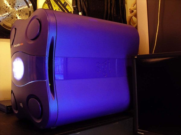
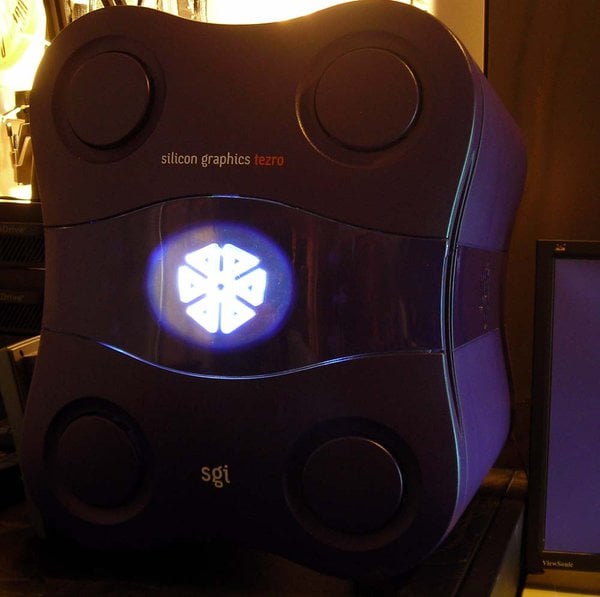
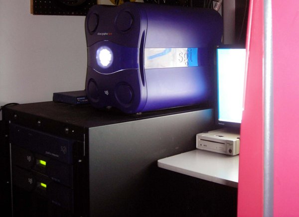
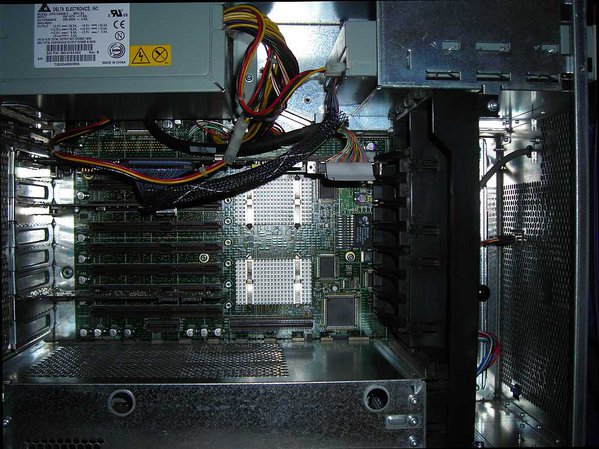
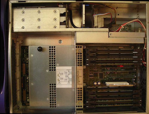
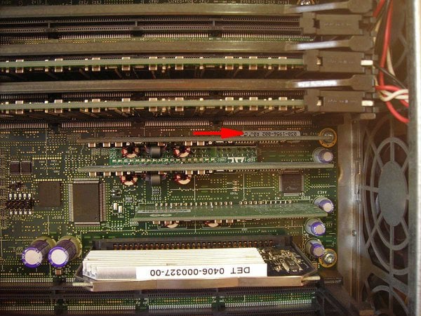
A few photos - some have said they don't care for the tower Tezro's case design, and I wonder if that partially due to the fact most photos are taken head-on. Now that I've seen one in person, I don't think most photos accurately depict the visual strength of the design. I found the Tezro's most striking feature to be it's proportions - particularly the less often seen profile:
***********************************************************************
Welcome to ARMLand - 0/0x0d00
running...(sherwood-root 0607201829)
* InfiniteReality/Reality Software, IRIX 6.5 Release *
***********************************************************************
Welcome to ARMLand - 0/0x0d00
running...(sherwood-root 0607201829)
* InfiniteReality/Reality Software, IRIX 6.5 Release *
***********************************************************************




 J5600, 2 x Mac, 3 x SUN, Alpha DS20E, Alpha 800 5/550, 3 x RS/6000, Amiga 4000 VideoToaster, Amiga4000 -030, 733MHz Sam440 AmigaOS 4.1 update 1.
 Tandem Himalaya S-Series Nonstop S72000 ServerNet.


 So, if you put a fan on TOP of anything, make it PULLING air and not BLOWING. It will have a higher CFM if you keep the normal flux of air.


