SGI: hinv

Tezro: 4x800Mhz | 8GB | V12 | DCD | 10GbE | SAS | USB | RAD

hinv -vm

Code: Select all

Location: /hw/module/001c01/node
IP53_4CPU Board: barcode NJA563     part 030-1959-003 rev -C
Location: /hw/module/001c01/IXbrick/xtalk/11
WS_INT_53 Board: barcode NRV419     part 030-1881-007 rev -A
Location: /hw/module/001c01/IXbrick/xtalk/12
ASTODY Board: barcode NNC015     part 030-1726-006 rev -A
Location: /hw/module/001c01/IXbrick/xtalk/15
WS_INT_53 Board: barcode NRV419     part 030-1881-007 rev -A
Location: /hw/module/001c01/IXbrick/xtalk/15/pci-x/0/1/ioc4
IO9 Board: barcode NRX083     part 030-1771-005 rev -B
4 800 MHZ IP35 Processors
CPU: MIPS R16000 Processor Chip Revision: 2.2
FPU: MIPS R16010 Floating Point Chip Revision: 2.2
CPU 0 at Module 001c01/Slot 0/Slice A: 800 Mhz MIPS R16000 Processor Chip (enabled)
Processor revision: 2.2. Scache: Size 8 MB Speed 400 Mhz  Tap 0xa
CPU 1 at Module 001c01/Slot 0/Slice B: 800 Mhz MIPS R16000 Processor Chip (enabled)
Processor revision: 2.2. Scache: Size 8 MB Speed 400 Mhz  Tap 0xa
CPU 2 at Module 001c01/Slot 0/Slice C: 800 Mhz MIPS R16000 Processor Chip (enabled)
Processor revision: 2.2. Scache: Size 8 MB Speed 400 Mhz  Tap 0xa
CPU 3 at Module 001c01/Slot 0/Slice D: 800 Mhz MIPS R16000 Processor Chip (enabled)
Processor revision: 2.2. Scache: Size 8 MB Speed 400 Mhz  Tap 0xa
Main memory size: 8192 Mbytes
Instruction cache size: 32 Kbytes
Data cache size: 32 Kbytes
Secondary unified instruction/data cache size: 8 Mbytes
Memory at Module 001c01/Slot 0: 8192 MB (enabled)
Bank 0 contains 1024 MB (Premium) DIMMS (enabled)
Bank 1 contains 1024 MB (Premium) DIMMS (enabled)
Bank 2 contains 1024 MB (Premium) DIMMS (enabled)
Bank 3 contains 1024 MB (Premium) DIMMS (enabled)
Bank 4 contains 1024 MB (Premium) DIMMS (enabled)
Bank 5 contains 1024 MB (Premium) DIMMS (enabled)
Bank 6 contains 1024 MB (Premium) DIMMS (enabled)
Bank 7 contains 1024 MB (Premium) DIMMS (enabled)
Integral SCSI controller 3: Version SAS/SATA LS1068
Integral SCSI controller 2: Version IDE (ATA/ATAPI) IOC4
CDROM: unit 0 on SCSI controller 2
Integral SCSI controller 0: Version QL12160, low voltage differential
Disk drive: unit 1 on SCSI controller 0 (unit 1)
Integral SCSI controller 1: Version QL12160, low voltage differential
IOC3/IOC4 serial port: tty3
IOC3/IOC4 serial port: tty4
Graphics board: V12
10 Gigabit Ethernet: xg1, module 001c01, 133 MHz PCIX bus 3 slot 1
Integral Gigabit Ethernet: tg0, module 001c01, PCI bus 1 slot 4
Iris Audio Processor: version MAD revision 1, number 1
Iris Audio Processor: version RAD revision 13.0, number 1
PCI Adapter ID (vendor 0x1000, device 0x0054) PCI slot 1
PCI Adapter ID (vendor 0x17d5, device 0x5831) PCI slot 1
PCI Adapter ID (vendor 0x10a9, device 0x100a) PCI slot 1
PCI Adapter ID (vendor 0x104c, device 0xac28) PCI slot 2
PCI Adapter ID (vendor 0x1077, device 0x1216) PCI slot 3
PCI Adapter ID (vendor 0x14e4, device 0x1645) PCI slot 4
PCI Adapter ID (vendor 0x1412, device 0x1724) PCI slot 2
PCI Adapter ID (vendor 0x10a9, device 0x0005) PCI slot 1
PCI Adapter ID (vendor 0x1033, device 0x0035) PCI slot 2
PCI Adapter ID (vendor 0x1033, device 0x00e0) PCI slot 2
IOC4 firmware revision 83
IOC3/IOC4 external interrupts: 1
HUB in Module 001c01/Slot 0: Revision 2 Speed 200.00 Mhz (enabled)
Dual Channel Display
IP35prom in Module 001c01/Slot n0: Revision 6.210
USB controller: type OHCI


gfxinfo -vv

Code: Select all

Graphics board 0 is "ODYSSEY" graphics.
Managed (":0.0") 3840x1200
BUZZ version B.2
PB&J version 1
128MB memory
Banks: 4, CAS latency: 3
Monitor 0 type: Unknown
Dual Channel Display option
Monitor 1 type: NEC 26450       Monitor 2 type: DEL -24390
Input Sync: Voltage - Video Level; Source - Internal; Genlocked - False
Channel 0:
Origin = (0,0)
Video Output: 1920 pixels, 1200 lines, 60.00Hz (2@1920x1200_60p)
Video Format Flags:  (none)
Sync Disabled
Using Gamma Map 0
Monitor Type:  NEC-26450
Gain (all color components) - 0.000000 ; range [1,10]
Channel 1:
Origin = (1920,0)
Video Output: 1920 pixels, 1200 lines, 60.00Hz (2@1920x1200_60p)
Video Format Flags:  (none)
Sync Disabled
Using Gamma Map 0
Monitor Type:  DEL-41146
Gain (all color components) - 0.000000 ; range [1,10]


uname -aR

Code: Select all

IRIX64 IRIS 6.5 6.5.30m 07202013 IP35


scsicontrol -i /dev/scsi/*

Code: Select all

/dev/scsi/sc0d1l0:  Disk          COMPAQ  BF1468B26B      HPB9
ANSI vers 3, ISO ver: 0, ECMA ver: 0; supports:  16bit synch cmdqueing
Device is  ready
/dev/scsi/sc2d0l0:  CD-ROM        MATSHITADVD-ROM SR-8589 8Z17
ANSI vers 0, ISO ver: 0, ECMA ver: 0; supports:
Device is  not ready


/sbin/diskpatch -v

Code: Select all

sc0d1l0:  Disk         COMPAQ  BF1468B26B      HPB9  Serial: 6LN04K7W


l1cmd serial all

Code: Select all

Data                            Location      Value
------------------------------  ------------  --------
Local System Serial Number      NVRAM         P1003490
Reference System Serial Number  NVRAM         P1003490
Local Brick Serial Number       EEPROM        NRV419
Reference Brick Serial Number   NVRAM         NRV419


EEPROM      Product Name    Serial         Part Number           Rev  T/W
----------  --------------  -------------  --------------------  ---  ------
INTERFACE   WS_INT_53       NRV419         030_1881_007          A    00
IO9         IO9             NRX083         030_1771_005          B    00
ODYSSEY     ASTODY          NNC015         030_1726_006          A    00
SNOWBALL    no hardware detected
NODE        IP53_4CPU       NJA563         030_1959_003          C    00
IO DGHTR    CHWS_IO_DAUG    NNV020         030_1875_003          A    00

EEPROM     JEDEC-SPD Info           Part Number        Rev  Speed  SGI
---------- ------------------------ ------------------ ---- ------ --------
DIMM 0     7F94FFFFFFFFFFFF0888980D SM57228DSGI100M    00FF   8.0  N/A
DIMM 2     7F94FFFFFFFFFFFF1888980D SM57228DSGI100M    00FF   8.0  N/A
DIMM 4     7F94FFFFFFFFFFFF936B101D SM57228DSGI100C2   00FF   8.0  N/A
DIMM 6     7F94FFFFFFFFFFFF836B101D SM57228DSGI100C2   00FF   8.0  N/A
DIMM 1     7F94FFFFFFFFFFFF1A88980D SM57228DSGI100M    00FF   8.0  N/A
DIMM 3     7F94FFFFFFFFFFFF2888980D SM57228DSGI100M    00FF   8.0  N/A
DIMM 5     7F94FFFFFFFFFFFF036B101D SM57228DSGI100C2   00FF   8.0  N/A
DIMM 7     7F94FFFFFFFFFFFF7D6B101D SM57228DSGI100C2   00FF   8.0  N/A


l1cmd flash status

Code: Select all

Flash image B currently booted

Image      Status        Revision    Built
-----   -------------   ----------   -----
A     valid           1.36.17      06/01/2005 14:43:15
B     default         1.36.17      06/01/2005 14:43:15


l1cmd env

Code: Select all

Environmental monitoring is enabled and running.

Description    State       Warning Limits     Fault Limits       Current
-------------- ----------  -----------------  -----------------  -------
1.8V    Enabled  10%   1.62/  1.98  20%   1.44/  2.16    1.791
12V    Enabled  10%  10.80/ 13.20  20%   9.60/ 14.40   12.063
12V #2    Enabled  10%  10.80/ 13.20  20%   9.60/ 14.40   12.188
3.3V    Enabled  10%   2.97/  3.63  20%   2.64/  3.96    3.337
2.5V    Enabled  10%   2.25/  2.75  20%   2.00/  3.00    2.496
12V IO    Enabled  10%  10.80/ 13.20  20%   9.60/ 14.40   12.063
5V AUX    Enabled  10%   4.50/  5.50  20%   4.00/  6.00    5.044
3.3V AUX    Enabled  10%   2.97/  3.63  20%   2.64/  3.96    3.268
5V    Enabled  10%   4.50/  5.50  20%   4.00/  6.00    5.148
XIO 12V BIAS    Enabled  10%  10.80/ 13.20  20%   9.60/ 14.40   12.000
XIO 5V    Enabled  10%   4.50/  5.50  20%   4.00/  6.00    5.122
XIO 2.5V    Enabled  10%   2.25/  2.75  20%   2.00/  3.00    2.457
XIO 3.3V AUX    Enabled  10%   2.97/  3.63  20%   2.64/  3.96    3.268
IP53 3.3V AUX    Enabled  10%   2.97/  3.63  20%   2.64/  3.96    3.285
IP53 5V AUX    Enabled  10%   4.50/  5.50  20%   4.00/  6.00    5.044
IP53 12V    Enabled  10%  10.80/ 13.20  20%   9.60/ 14.40   12.000
IP53 VCPU    Enabled  10%   1.13/  1.38  20%   1.00/  1.50    1.241
IP53 SRAM    Enabled  10%   2.25/  2.75  20%   2.00/  3.00    2.470
IP53 1.5V    Enabled  10%   1.35/  1.65  20%   1.20/  1.80    1.480

Description     State       Warning RPM  Current RPM
--------------- ----------  -----------  -----------
FAN  0   NODE 1    Enabled         1800         2235
FAN  1   NODE 2    Enabled         1800         2191
FAN  2   NODE 3    Enabled         1800         2250
FAN  3    PCI 1    Enabled         1350         1548
FAN  4    PCI 2    Enabled         1350         1548
FAN  5       HD    Enabled         1620         3668
FAN  6    ODY 1    Enabled         1300         1704
FAN  7    ODY 2    Enabled         1300         1591

Advisory   Critical   Fault      Current
Description       State       Temp       Temp       Temp       Temp
----------------- ----------  ---------  ---------  ---------  ---------
0 INTERFACE 0       Enabled    [Autofan Control]    76C/168F   36C/ 96F
1 INTERFACE 1       Enabled    [Autofan Control]    76C/168F   31C/ 87F
2 INTERFACE 2       Enabled    [Autofan Control]    76C/168F   31C/ 87F
3 INTERFACE 3       Enabled    [Autofan Control]    76C/168F   38C/100F
4 ODYSSEY           Enabled    [Autofan Control]    76C/168F   42C/107F
5 NODE              Enabled    [Autofan Control]    76C/168F   50C/122F
6 BEDROCK           Enabled    [Autofan Control]    85C/185F   50C/122F

Zone Temp     Target    Current   Zone Fan   Curr/Min
Zone Name  State     Sensors       Average   Average   Index      Fan %
---------  --------  ------------  --------  --------  ---------  ---------
Node        Enabled           5,6  62C/143F  50C/122F          0   46%/ 46%
PCI         Enabled       0,1,2,3  45C/113F  34C/ 93F        3,4   57%/ 57%
ODY         Enabled             4  50C/122F  42C/107F          6   64%/ 64%
HD          Enabled             5  40C/104F  50C/122F          5   66%/ 38%


l1cmd pci

Code: Select all


Bus Slot Stat    Power Mode/Speed
--- ---- ------- ----- -----------
1    1 0x80 01   15W PCI   66MHz
2    1 0x00 00  7.5W PCI   33MHz
2    2 0x00 00  7.5W PCI   33MHz
2    3 0x00 0f  none PCI   33MHz
3    1 0x00 0e   25W PCIX 133MHz
3    2 0x00 0f  none PCIX 133MHz
4    1 0x00 0c  7.5W PCIX 133MHz
4    2 0x00 0f  none PCIX 133MHz


Notes:
- The S2iO 10Gb Ethernet card is running at pretty high temperature
- It appears that opening the left side of the case (the one with VPro & PSU) lowers the temperature, while opening the right side (with CPUs and RAM) rises it and the machine shuts down.
oOoO :Tezro: oOoO
Very nice, congratulations!
devv wrote: Notes:
- The S2iO 10Gb Ethernet card is running at pretty high temperature
- It appears that opening the left side of the case (the one with VPro & PSU) lowers the temperature, while opening the right side (with CPUs and RAM) rises it and the machine shuts down.
I bucked the less-fan-noise trend and added fans to mine ;) .
***********************************************************************
Welcome to ARMLand - 0/0x0d00
running...(sherwood-root 0607201829)
* InfiniteReality/Reality Software, IRIX 6.5 Release *
***********************************************************************
Hehe, sure, I've been watching that thread. I'll sure try doing that as well; the point I'm kind of stuck at at the moment is locating the pins to which I should connect the fan I'd add above the VPro.
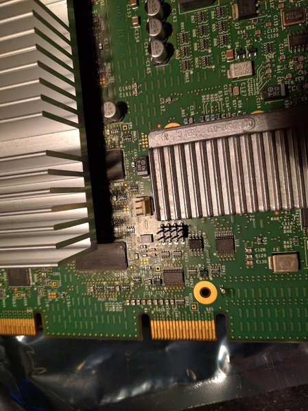
Actually I just found it -- as you said "SGI included an <unused> three-pin fan header on the Tezro version of the V12 that isn't present on the Fuel version of the V12.".
I'll try to follow what you did there and fill in with any other info if I find something new/untried yet or some good fans. Thanks!
oOoO :Tezro: oOoO
Actually, recondas -- where is that 3-pin fan header? I've opened the cover of the VPro and I only see two connectors of which none seem to be it.
There is a 2-pin header between the two heatsinks, and there is a 6-pin header deeper above the larger heatsink, close to the PCI-X attachment.
I don't see anything with 3 pins.

Also, is the header a standard 3-pin fan or I need to change the order of wires as shown in viewtopic.php?f=3&t=9046 ?
oOoO :Tezro: oOoO
I've played a bit with determining the effect of additional fans on the temperature.

In the tests, I've been measuring:
- With and without the left panel (the one on the VPro side) being present
- With and without the VPro cover being present
- With and without additional fan present (used Noctua NF-P14, running at 1200 RPM: http://noctua.at/en/nf-p14-flx/specification )

Overall, it appears that the largest positive influence on the temperature has the removal of the left panel.
Without it installed, it is possible to achieve the lowest temperature of the VPro, as well as the fact that it also reduces the temperature of BEDROCK by about 5 C and of NODE by 2-3 C without me doing anything to them.

So, temperature of "4 ODYSSEY" in various combinations (in order of best first):

- Without panel, without cover, fan on top (perpendicular to case air flow): 32 C (image of this setup it attached)
- Without panel, without cover, fan parallel (in the direction of air flow): 34 C
- With panel, with cover, fan on top: 36-37 C
- With panel, without cover, fan parallel: 36-37 C
- With panel, without cover, fan on top: 36-37 C
- Without panel, with cover, no fan: 39 C
- With panel, with cover, no fan: 42+ C (this is standard setup without modification)

Notes:
- I did not examine the effects if the front panel is removed rather than the left panel.
- I did confirm that removing the right panel (one on the CPUs/RAM side) quickly increases temperature of BEDROCK, and then initiates shutdown. (So as mentioned, removing the left panel is beneficial, while removing the right is not).
- The image of the most effective variant found (reaching down to 32 C) is attached.

Additional mini-chapter:
- I did not find the 3-pin fan connector on the VPro. Instead, I've plugged a dedicated fan control box in between the PSU 12V power and the DVD drive. (I happened to have this fan controller handy: http://sun-trust.net/products/scythe/1068.html ).
- I actually like this approach best and it does not require modifying the fans since they're connected to a compatible controller.
- The only drawback is that if one wants to replace Tezro's DVD drive with a 1x5.25 -> 4.x2.5 SAS/SATA drive enclosure (such as Icy Dock MB994SP-4SB-1 or Logilink UA0208), then there may not be enough depth available to mount both the drives enclosure in the back and the fan control in the front of the 5.25 slot. (In the attached image, it can be seen that there is only little unused depth remaining between the end of the DVD and start of the PSU, although it might be just enough - didn't try yet!).
oOoO :Tezro: oOoO
Dude, where's the (plastic) skin(s)?
smit happens.

:Fuel: bigred , 900MHz R16K, 4GB RAM, V12 DCD, 6.5.30
:Indy: indy , 150MHz R4400SC, 256MB RAM, XL24, 6.5.10
:Indigo2IMP: purplehaze , 175MHz R10000, Solid IMPACT
probably posted from Image bruce , Quad 2.5GHz PowerPC 970MP, 16GB RAM, Mac OS X 10.4.11
plus IBM POWER6 p520 * Apple Network Server 500 * RDI PrecisionBook * BeBox * Solbourne S3000 * Commodore 128 * many more...
I've taken it off, my mini-goal here was to measure temperatures, and without the left panel (skin) I was able to produce the lowest temp.
Will post some more pics of it tomorrow, in a more proper dressing :)
oOoO :Tezro: oOoO
Nice! Congratulations.
:PI: :Indigo: :Indigo: :Indy: :Indy: :Indy: :Indigo2: :Indigo2: :Indigo2IMP: :Octane: :Octane2: :O2: :O2+: Image :Fuel: :Tezro: :4D70G: :Skywriter: :PWRSeries: :Crimson: :ChallengeL: :Onyx: :O200: :Onyx2: :O3x02L:
To accentuate the special identity of the IRIS 4D/70, Silicon Graphics' designers selected a new color palette. The machine's coating blends dark grey, raspberry and beige colors into a pleasing harmony. ( IRIS 4D/70 Superworkstation Technical Report )
Outstanding machine old chap. Does that peak SGI Workstations?
-----------------------------------------------------------------------
Hey Ho! Pip & Dandy!
:Octane2: :O2: :Indigo: :Indy:
-----------------------------------------------------------------------
I wish :) Still hunting for 4x1Ghz instead of 4x800Mhz. But I have a feeling that'll be postponed for a couple years, given the prices of 4x1Ghz boards :)
oOoO :Tezro: oOoO
What's 200MHz(x4) among friends ;)
-----------------------------------------------------------------------
Hey Ho! Pip & Dandy!
:Octane2: :O2: :Indigo: :Indy:
-----------------------------------------------------------------------
Last time I checked, it was about 1500 EUR :)
oOoO :Tezro: oOoO
Less than a night with a high class prostitute.. but lasts forever I say!
-----------------------------------------------------------------------
Hey Ho! Pip & Dandy!
:Octane2: :O2: :Indigo: :Indy:
-----------------------------------------------------------------------
devv wrote: Actually, recondas -- where is that 3-pin fan header?
The fan header is located between the small and large heat sinks . The part number for that dead-on-arrival / fan-header-included V12 is 030-1884-002, revision D.

Sorry for the confusion - the initial post in that thread (with the hinv and other data) was updated over time as I made changes to the configuration. What you may not notice because of the updates to the hinv is when I acquired that Tezro the original V12 was dead (also doesn't help that the underlying story about the acquisition/resurrection of that Tezro is located in another thread).

So while the original V12 did indeed have a three-pin fan header, I installed and ran a Fuel V12 (without an integrated fan header) for a year and a half. So I powered the supplemental fans in much the same way as you did; with a molex power splitter :
in his Tezro hinv post, recondas wrote: I didn't have any 60mm fans <nor did any of the sources local to me>, but I did have two 38mm fans pre-wired in a two-fan array with a molex-splitter power attachment. For initial testing I zip-tied the 38mm fans to the perforated metal shielding, directly in front and blowing onto the perforations in the node board cooling shroud, and made an air duct so that air was directed into the openings in the node board shroud <rather than the dead air space above the shroud. The molex splitter was connected at the <molex> power feed for the hard drive backplane <located directly above the node board>. The 38mm fans are only rated at 4.5CFM each <I plan to order three 12CFM-each low-DBA 60mm fans as replacements>, but made a noticeable 6C/11F drop in the operating temperature of the bedrock a ASIC.

In the time since that was written I've replaced the 38mm fans by the node board cooling shroud with two 60mm fans ( 1GHz node boards come from the factory with cooling fans located in a similar position ). I still have the 80mm fan mounted on top of the perforated V12 cooling shroud, and I moved the two 38mm fans mentioned above to exhaust air through the perforated bulkhead at the back of the PCI cage. All are still powered via molex splitters.
***********************************************************************
Welcome to ARMLand - 0/0x0d00
running...(sherwood-root 0607201829)
* InfiniteReality/Reality Software, IRIX 6.5 Release *
***********************************************************************
Well that's interesting, my V12 has a 2-pin header in place of the 3-pin fan header. I will check on the part number etc.
Great, thanks for the tips.
oOoO :Tezro: oOoO