The collected works of zuluchas - Page 1

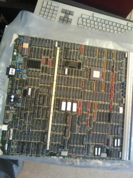
Considering the case has "Sep 1989" stamped on it in several places, this twin-tower beast is in pretty good shape. It powers up just fine, and I've rigged up a serial port converter according to this page:
http://www.meadow.net/pinouts.html#sgikeydb9

Connecting a VT220 to the first serial port given me the (surprisingly) familiar POST messages:
Code:
Version 4D1-4.0A IP7 OPT Tue May  2 11:26:34 PDT 1989 SGI

Memory address pattern test from B0000000 to B0014000
Looking for additional CPUs!
CPU 1 recognized
CPU 2 recognized
CPU 3 recognized
Total of 4 CPUs running!
Testing all UART's ports                        PASSED.
Timer/Clock                                     PASSED.
Floating Point Unit                             PASSED.
Sync Bus Controller                             PASSED.
I/O Mapper, INT Vectors, MODE Regs              PASSED.
SCSI Controller                                 PASSED.
Data and Instruction Caches                     PASSED.
Full Memory Test                                PASSED.
MP Caches                                       PASSED.
Initialize local hardware!

CPU     LOCAL DIAG      1st CACHE       MEMORY          MP CACHES
0       Passed          Passed          Passed          Passed
1       Passed          Passed          Passed          Passed
2       Passed          Passed          Passed          Passed
3       Passed          Passed          Passed          Passed

Sizing and clearing 56 Mbytes of memory!   Initialize local hardware!
Loading Monitor ... Done!
nv ram checksum incorrect, check with printenv and fix with 'setenv ENV_VAR'
where ENV_VAR is a non-volatile environment variable such as bootmode

Error-- keyboard not responding

Error-- cannot open console "gfx(0)"


System Maintenance Menu
1) Start System
2) Install System Software
3) Run Diagnostics
4) Recover System
5) Enter Command Monitor

Option?


I have also connected the same serial adapter to the serial port on one of the GM. It prints out a sequence of POST messages and concludes with:
Code:
GM PROM diags PASSED.

It prints this series of messages twice, actually, on first power-up. Then it presents a prompt-looking "gm>" but doesn't take any input.

The LED status digit near the front power switch alternates between 1 and 2 continuously. This is normal while in PROM, right?

There's no keyboard attached, so I expect the no keyboard and gfx(0) errors. All the other diagnostics seem to pass, but I'm experiencing two problems:
1) I am unable to enter anything into the terminal -- it doesn't accept or respond to any input over the VT.
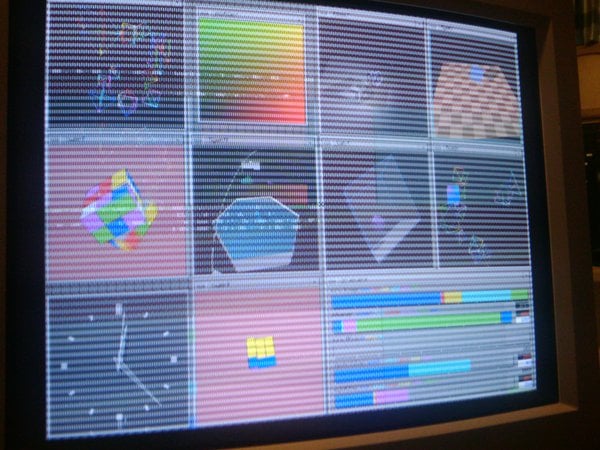
2) When plugging in a monitor using the primary graphics output, I'm presented with a garbled, black and white console screen which echoes the output on the serial port. You can almost make out what's on the screen, but clearly there's some thing wrong with the graphics subsystem.

I have a couple old SGI keyboards from this era, and am planning to make a keyboard adapter as well. But beyond that, I'm not sure where to begin troubleshooting the console and graphics issues. I hope it's salvageable! The lack of SGI documentation is unfortunate -- or can anyone point me to a reference more specific than This Old SGI (which is excellent but doesn't have a lot of detail about this system and the options available)? Are there scans of the original docs somewhere?

Also, is http://sgistuff.g-lenerz.de/ down or is it just me? (I just get a "500 Internal Server Error" message.)

I'll post some pics on here if I can figure out how to do that... :)

Cheers!

_________________
:Onyx2RM: :Onyx2: :O200: :4D70G: :Fuel: :Indigo: :Octane2: :O2: :Indigo2: :Indy:
I put together a keyboard adapter and am now able to communicate with the PROM. Unfortunately, I'll be away for a while so won't have time to put together a new serial adapter and re-test. I did use the layout listed in the link you mentioned (#sgiDB9F) but had moved on to the keyboard link since that was the next project. I've got IRIX 3.3.2 on tape, which I'd like to try out, as well as 4.0.something. I've also managed to pick up a Crimson with VGX, so may try swapping in the graphics boards -- I assume this is a valid combination for the 4d/240 since it supports VGX, right? Would I have to upgrade the frontplane as well?

Here are the PNs for the boards currently installed in the 4d/240 and some pics:
013-0206-001 (tape controller)
013-0203-003 (disk controller)
030-0118-001 (IO2)
2x 030-0135-001 (dual R3k @ 25MHz boards)
030-0117-001 (MC2)
030-0154-003 (RV1.5 w/o alpha)
030-0078-002 (RM1 w/o alpha)
030-0078-001 (RM1 w/ alpha)
030-0075-001 (GE4)
030-0116-002 (some unlisted graphics option board with 2x RGBS BNC, 2x "composite" BNC, and DB-9 "trigger" ports)
030-0139-001 (frontplane)

Sorry the pics are crappy -- they're from a phone camera.

On another note, the two stackable drive bays are slightly different from one another on the inside. It looks like you could just keep stacking them on up, although I've never seen a pic with more than two shown. Does anyone know if there was a limit to the number of bays stackable on a system, and which is supposed to be the top bay of the two (if there is a preferred top bay).

In the prom, the tape drive is recognized by hinv. I haven't had a chance to install a SCSI HDD or anything else yet. I tried reseating the connector boards and the problem got worse! Will reseat again and see how it goes, but looks like this may be another version of the pinstripe issue. :(

_________________
:Onyx2RM: :Onyx2: :O200: :4D70G: :Fuel: :Indigo: :Octane2: :O2: :Indigo2: :Indy:
Hehe, yeah, that and this phone camera needs full daylight conditions to take decent pics...but there's only so much a halogen lamp can do for you at night!

The collection is growing but floor space is not keeping pace!

_________________
:Onyx2RM: :Onyx2: :O200: :4D70G: :Fuel: :Indigo: :Octane2: :O2: :Indigo2: :Indy:
Okay, I've gotten the serial console to work. I ended up going with the DB9M-DB25F configuration and realized I didn't need a null modem to get it working with the VT220. That did the trick, so I could theoretically do some real troubleshooting. I will stick a 2GB drive in see if I can netboot it on 5.3. @jan-japp, I guess I'm ready for the 5.3 diagnostics!

I've got the serial cable hooked up to the GM board and can communicate with it just fine as well. There is a "test" function, but not sure what to do with it.

_________________
:Onyx2RM: :Onyx2: :O200: :4D70G: :Fuel: :Indigo: :Octane2: :O2: :Indigo2: :Indy:
A couple of updates:

I've been able to netboot sash 3.3.2 and 5.3 over ethernet (using an AUI-10bT adapter) from the onyx2. I've had a few issues copying the miniroot over the net, though I think they are more SCSI- than net-related.

I've found a few differences between my experience and the This Old SGI notes about booting and about using CD-ROMs. One thing I noticed was that I couldn't boot to an arbitrary file via the boot command in the PROM. I had to specify the boot path beforehand via the environment variable "bootfile" and then just time "boot". Although the SCSI CD drive was recognized as an "unknown / removable" scsi device, I couldn't figure out how to boot sash from it. I tried dksc(0,6,8)sash.IP7 and scsi(0,6,8)sash.IP7 with no luck. Once I netbooted sash 5.3, there was no problem addressing the cd drive as dksc(0,6,x).

I think the SCSI cabling may be in disarray. I'm not sure what the recommended layout is, but when I tried what seemed to make sense, it didn't work. When I received the system, there was a standard 50-pin internal SCSI ribbon cable running from the controller to the drive tower. There it got weird. The tower's sideplane was connected at the second-to-last port on that cable, then the tape drive as the next-to-last, and nothing on the end. That would seem to form a "Y", wouldn't it? Not so good for SCSI, but switching the sideplane to the last plug on the ribbon didn't work. By keeping the original Y configuration and adding a drive to the last plug (with termination on) and an ID of 2 (not 1, that doesn't work) I've got a working configuration with a tape at ID 7 and a drive at ID 2. I could then add a SCSI CD in the first stackable drive unit on top at ID 6. As mentioned before, the two stackable modules are slightly different in their layout and SCSI cabling, and I'm wondering if there is a right or wrong ordering for stacking them. The one I tested with has two 50-pin scsi connectors on the sideplane; the other module has only one. It seems to work (as in, hinv finally recognizes three scsi devices), but then I have trouble copying the miniroot to disk with SCSI timeout errors and such.

I've attached some pics of the modules and cabling for reference.

SCSI to-do: try different stackable module configurations, different SCSI HDDs, take the tape out and examine the jumpers to figure out what it's SCSI settings are.

In terms of graphics, I've taken all the boards out and examine their pins. None are broken, bent, or missing. When I remove the RM boards from the system, the symptoms change but do not improve: essentially the screen is much whiter, but just as garbled. Looks like the GTX is on its last legs.

I can confirm that that "unidentified" board is labeled VP1. And, yes, there's a GM2 in there as well.

Gfx to-do: try the crimson's VGX boards in the 240?

Unfortunately, I'll be away from tomorrow for a long while. Any thoughts appreciated in the meantime!

_________________
:Onyx2RM: :Onyx2: :O200: :4D70G: :Fuel: :Indigo: :Octane2: :O2: :Indigo2: :Indy:
I'll try those combinations. I was unable to get the drive to be recognized at ID 1 even with the tape removed from the chain. It showed up in hinv as occupying every SCSI ID on the bus instead.

Do I understand correctly that the last SCSI device in the chain is the one that needs the "TERM" jumper for SCSI buses w/o an actual physical terminator? That's one of the reasons I'm confused by the apparent Y cabling configuration. Does anyone know how these drive tower sideplanes actually work? Are they just a straight SCSI bus extension or do they act as a SCSI device proxy for everything attached above (that would be weird!)?

_________________
:Onyx2RM: :Onyx2: :O200: :4D70G: :Fuel: :Indigo: :Octane2: :O2: :Indigo2: :Indy:
BTW, Patch 7228 has been replaced by 7234 as of 6 Nov '09 and is available for dl from supportfolio. Good to see SGI's still giving some support!

I tried using sgisync to pick it up, but got no joy with version 0.64.

On an octane running 6.5.22 (unpatched), I had mixed results:

Code:
charmed 1# dig +short txidtest.dns-oarc.net TXT
txidtest.y.x.w.v.u.t.s.r.q.p.o.n.m.l.k.j.i.h.g.f.e.d.c.b.a.pt.dns-oarc.net.
"1.2.3.4 is GREAT: 26 queries in 2.7 seconds from 26 txids with std dev 17795"
charmed 2# uname -aR
IRIX64 charmed 6.5 6.5.22m 10070055 IP30
charmed 3# dig +short porttest.dns-oarc.net TXT
porttest.y.x.w.v.u.t.s.r.q.p.o.n.m.l.k.j.i.h.g.f.e.d.c.b.a.pt.dns-oarc.net.
"1.2.3.4 is POOR: 26 queries in 2.7 seconds from 26 ports with std dev 8"
charmed 4#


I won't get around to trying out this patch anytime soon, but hope it helps someone!

_________________
:A350R: :Onyx2: :4D220VGX: :Fuel: :Indigo: :Octane2: :O2: :O3x0: :Indy:
+1

_________________
:Onyx2RM: :Onyx2: :O200: :4D70G: :Fuel: :Indigo: :Octane2: :O2: :Indigo2: :Indy:
She's up and running IRIX 3.3.2 now!

viewtopic.php?f=7&t=16722120

And with some part swaps is a pretty functional 4d/240 VGX. Now to do something about a mouse....

_________________
:Onyx2RM: :Onyx2: :O200: :4D70G: :Fuel: :Indigo: :Octane2: :O2: :Indigo2: :Indy:
I've got some 8MB sticks for the MC2, so I took out all of the old 2MB ones first. I've been reading old posts here and discovered that you can mix 8mb and 2mb sticks (contrary to This Old SGI), but that there are some limitations.

Success mixing RAM sizes on MC2, suggests limitation is in PROM version:
viewtopic.php?f=5&t=6727&hilit=mc2

Well, what I found was then when I put known perfectly good 8MB sticks in the MC2, they came up as 2MB! I tried it with 8x 8MB sticks, arranged in matching adjacent pairs, each set of four identical -- the 4D sees 16MB. I tried it with 12x 8MB and got "24MB." This is without any 2MB sticks in at all, so it has nothing to do with the supposed inability to mix 8MB and 2MB on the same board.

Is this a PROM version limitation, as suggested in the above post? Or am I missing something?
I don't see any jumpers on the MC2 to change ram type. I don't see any PROM settings or commands. The "resetenv" command suggested earlier does not exist.

The MC2 board is P/N: 030-0117-001 rev D, so maybe too early a version for 8MB sticks?

When first turned on, the 4D comes up with:
Code:
Version 4D1-4.0A IP7 OPT Tue May  2 11:26:34 PDT 1989 SGI


Then in the PROM, the version given is:
Code:
PROM Monitor Version 4D1-4.0A PROM IP5 OPT Fri Jul 14 09:28:31 PDT 1989 SGI

_________________
:Onyx2RM: :Onyx2: :O200: :4D70G: :Fuel: :Indigo: :Octane2: :O2: :Indigo2: :Indy:
I'm thinking that the PROM must be the problem for the MC2 board. I look forward to hearing what you find in the attic, Jan-jaap!

Just out of interest, I'll try replicating the IP17 mix of 8MB and 2MB on the same board (in the Crimson, of course, not the 4D) and let you know what happens (and what version of the PROM that system is using).

_________________
:Onyx2RM: :Onyx2: :O200: :4D70G: :Fuel: :Indigo: :Octane2: :O2: :Indigo2: :Indy:
jan-jaap wrote:
MC2's in storage:
1 * 030-0117-034 rev B (with 32*2MB SIMMs installed).
2 * 030-0117-026 rev A.
1 * 030-0117-009 rev A.


Is there any chance you might be able to test one or more of the MC2s in storage with 8MB simms in ony of the 4d systems? We've got a great selection of boards to work with here -- now I'm really excited to see if we can pin this down to board numbers and/or PROM revisions!

_________________
:Onyx2RM: :Onyx2: :O200: :4D70G: :Fuel: :Indigo: :Octane2: :O2: :Indigo2: :Indy:
jan-jaap wrote:
I can do that, but I'm not sure there's a lot to be learned from this exercise:

* If 8MB SIMM support was added to some MC2 rev, it must have been rev -010 or earlier. After all, it works in the Predator (030-0117-010 rev A). So the -034 and -026 boards will support it as well.


Ah, okay, well at least we have a baseline (-010).

Quote:
* The earliest specimen I have is the -009 board in storage. I could try that one, but if it works, it still does not give conclusive proof whether your problem is due to your even older MC2 rev, or your older IP5/IO2 PROM revision. Only if the -009 board works with 2MB SIMMs but not 8MB SIMMs do we learn anything.


True, although I was thinking more in terms of if you were still interested in sending me one of them -- it'd be good to know that they did work with 8mb simms so I could then diagnose the issue as either a board or a PROM rev problem.

Quote:
Something else: "This old SGI" says the SIMMs have to be installed in banks of 4 . You did not mix two 2MB and two 8MB SIMMs in one bank, did you? Oh, and unlike what "This old SGI" may suggest, an MC3 belongs in an Onyx, not in a PowerSeries :)


Yes, they were installed in sets of 4. I first tried them with 8 then with 12. They were installed in matching quads, starting from the side of the board with status LEDs, as described in "this old sgi." With eight it, it showed 16mb; with 12 it showed 24mb. So it's proportional to the number of simms, but 1/4th the total expected! No mixing of 2mb and 8mb modules -- just straight 8mb. Yes, the MC3 reference is a bit confusing.

Quote:
I have dumps of the IP5 and the IO2 PROMs, but these were created by dumping the relevant address range on the system itself, not by pulling the EPROM chips out and reading them in in an EPROM burner. So, I have one file for the IP5 PROM but in reality it's 4 chips and I wouldn't know how to split the data and create 4 new chips. Same for he IO2 PROM.


Yes, I have a feeling this is likely to be tricky without some specialized hardware and several posts to nekochan! More of a long-term project, perhaps? I do have an IO3, so maybe it would be worth trying the IP7+MC2+IO3 to see what happens?

_________________
:Onyx2RM: :Onyx2: :O200: :4D70G: :Fuel: :Indigo: :Octane2: :O2: :Indigo2: :Indy:
Gerhard.Lenerz wrote:
If it provides any insight I can check if a machine comes up nicely with one of the old rev MC2 installed.


Yes, thank you -- that would be great! Mine is -001, so really old!

_________________
:Onyx2RM: :Onyx2: :O200: :4D70G: :Fuel: :Indigo: :Octane2: :O2: :Indigo2: :Indy:
A few updates:

The system is not up and running as a 4D/240VGX and IRIX 3.3.2! The SCSI bus issue was due to a bad jumper on the SCSI ID pins of one drive, it turned out. I'm still doing some investigation on the stackable drive modules.

For those that might be interested:
I ended up running the 5.3 diags on the GTX and it appears that the GM2 board may be the culprit for this particular GTX issue:

Code:
Mon Jul 17 11:26:49 PDT 1995
INFO:   (200)   GM2 Memory test:  Starting Pixel DMA test (about 90 seconds)
INFO:   (200)   GM2 Memory test:  Host to GM to Host Memory DMA test PASSED
INFO:   (311)   PP<-->GM Handshake test: Zero, Marching 1
INFO:   (311)   PP<-->GM Handshake test: FF and Marching 0
INFO:   (312)   PP Branch test: PP branch test: Zero and Marching 1
INFO:   (312)   PP Branch test: PP branch test: Marching 0
INFO:   (313)   PP Stack test: PP stack level 1 test: Zero and Marching 1
INFO:   (313)   PP Stack test: PP stack level 1 test: Marching 0
INFO:   (313)   PP Stack test: PP stack level 2 test: Zero and Marching 1
INFO:   (313)   PP Stack test: PP stack level 2 test: Marching 0
INFO:   (317)   PP DIAG test: GM WC Reg test
INFO:   (317)   PP DIAG test: Source bus tests
INFO:   (317)   PP DIAG test: PP ALU tests
INFO:   (317)   PP DIAG test: Wordcount tests
INFO:   (317)   PP DIAG test: Condition tests
INFO:   (317)   PP DIAG test: Vertex pointer test
INFO:   (315)   PP SRAM test: OK: PP sram[0] write
INFO:   (315)   PP SRAM test: OK: PP sram[0] read
INFO:   (315)   PP SRAM test: OK: PP sram[1] write
INFO:   (315)   PP SRAM test: OK: PP sram[1] read
INFO:   (315)   PP SRAM test: Beginning slow SRAM tests
INFO:   (315)   PP SRAM test: Slow test: Begin marching 1 from low order bit
INFO:   (315)   PP SRAM test: Slow test: Begin marching 1 from high order bit
INFO:   (315)   PP SRAM test: Slow test: Begin marching 0 from low order bit
INFO:   (315)   PP SRAM test: Slow test: Begin marching 0 from high order bit
INFO:   (350)   GM2 EP Reset test
INFO:   (350)   GM2 EP Sequencer tests
INFO:   (350)   GM2 EP Data test
INFO:   (350)   GM2 EP Pixelbus test: Testing SP command sanity
INFO:   (350)   GM2 EP Pixelbus test: Testing Y path on pixel bus
INFO:   (350)   GM2 EP Pixelbus test: writing Y path
INFO:   (350)   GM2 EP Pixelbus test: reading Y path
INFO:   (350)   GM2 EP Pixelbus test: Testing X path
INFO:   (350)   GM2 EP Pixelbus test: writing X path
INFO:   (350)   GM2 EP Pixelbus test: reading X path
ERROR:   (350)   GM2 EP Pixelbus test: SP X error: x = 2, y = 0, exp 0x00000002  rcv 0x00000001
07/17/95(11:29:45)
...

(lots of these errors)

Code:
...
ERROR:   (350)   GM2 EP Pixelbus test: SP X error: x = 1278, y = 0, exp 0x000004FE  rcv 0x0000027E
07/17/95(11:30:24)
INFO:   (350)   GM2 EP Pixelbus test: Testing line stipple
ERROR:   (350)   GM2 EP Pixelbus test: Line stipple error: pos 32, exp 0x00000000  rcv 0xFFFFFFFF
07/17/95(11:30:24)
...

(lots of these errors, too, then a lot of successes on other parts of the gfx subsys, then ending with)

Code:
...
CompLoop datecode: February 26, 1992
CompLoop: GE4 has NEW WEITEK 3332s installed
[1] 887
CompLoop: no alpha channel detected

/usr/tmp/grid /usr/diags/gold/nagrid.n differ: char 54, line 3
CompGrid: FAILED

BAD  - Span 1: ffffec40 fffffb04 fffffb04 fffffb04
GOOD - Span 1: bfffec40 fbfffb04 fbfffb04 fbfffb04

BAD  - Span 2: fffffb04 fffffb04 fffffb04 ffffec40
GOOD - Span 2: bfffec40 2dfffad2 c9fffb36 fbfffb04

BAD  - Span 3: 6d6718c0 5dcce1cc 5e334478 7a0004b3
GOOD - Span 3: bfffec40 fbfffb04 fbfffb04 fbfffb04

/usr/tmp/rcip /usr/diags/gold/narcip.n differ: char 98, line 4
CompRecip: FAILED

BAD  - Span 2: ec67d317 3d62255c 75e0fe0d 8d1460ad
GOOD - Span 2: 90d9d691 f19026d2 3018dc93 7a2e630d

BAD  - Span 3: f2cbc7fb 9f9d5e48 f7a93549 a544c35c
GOOD - Span 3: 9336589d f5ea5c60 23704c9e 7f855076

/usr/tmp/grid /usr/diags/gold/nagrid.n differ: char 54, line 3
CompGrid: FAILED

BAD  - Span 1: ffffec40 fffffb04 fffffb04 fffffb04
GOOD - Span 1: bfffec40 fbfffb04 fbfffb04 fbfffb04

BAD  - Span 2: fffffb04 fffffb04 fffffb04 ffffec40
GOOD - Span 2: bfffec40 2dfffad2 c9fffb36 fbfffb04

BAD  - Span 3: 2f6712e1 31334746 2799ab31 67ccd20a
GOOD - Span 3: bfffec40 fbfffb04 fbfffb04 fbfffb04

/usr/tmp/rcip /usr/diags/gold/narcip.n differ: char 98, line 4
CompRecip: FAILED

BAD  - Span 2: ec67d317 3d62255c 75e0fe0d 8d1460ad
GOOD - Span 2: 90d9d691 f19026d2 3018dc93 7a2e630d

BAD  - Span 3: ea1c2c1c 9ae34191 f3c1e932 a0e8efd1
GOOD - Span 3: 9336589d f5ea5c60 23704c9e 7f855076

/usr/tmp/grid /usr/diags/gold/nagrid.n differ: char 54, line 3
CompGrid: FAILED

BAD  - Span 1: ffffec40 fffffb04 fffffb04 fffffb04
GOOD - Span 1: bfffec40 fbfffb04 fbfffb04 fbfffb04

BAD  - Span 2: fffffb04 fffffb04 fffffb04 ffffec40
GOOD - Span 2: bfffec40 2dfffad2 c9fffb36 fbfffb04

BAD  - Span 3: 3d33df7d 3f00153f 34001184 7300051d
GOOD - Span 3: bfffec40 fbfffb04 fbfffb04 fbfffb04

/usr/tmp/rcip /usr/diags/gold/narcip.n differ: char 98, line 4
CompRecip: FAILED

BAD  - Span 2: ec67d317 3d62255c 75e0fe0d 8d1460ad
GOOD - Span 2: 90d9d691 f19026d2 3018dc93 7a2e630d

BAD  - Span 3: eeff1700 a0da7109 f6af7e18 a7bbe0f8
GOOD - Span 3: 9336589d f5ea5c60 23704c9e 7f855076

/usr/tmp/grid /usr/diags/gold/nagrid.n differ: char 54, line 3
CompGrid: FAILED

BAD  - Span 1: ffffec40 fffffb04 fffffb04 fffffb04
GOOD - Span 1: bfffec40 fbfffb04 fbfffb04 fbfffb04

BAD  - Span 2: fffffb04 fffffb04 fffffb04 ffffec40
GOOD - Span 2: bfffec40 2dfffad2 c9fffb36 fbfffb04

BAD  - Span 3: 57671234 2433461d 19667779 543337d5
GOOD - Span 3: bfffec40 fbfffb04 fbfffb04 fbfffb04

/usr/tmp/rcip /usr/diags/gold/narcip.n differ: char 98, line 4
CompRecip: FAILED

BAD  - Span 2: ec67d317 3d62255c 75e0fe0d 8d1460ad
GOOD - Span 2: 90d9d691 f19026d2 3018dc93 7a2e630d

BAD  - Span 3: deb6caf3 839c4ce0 e55e0ae8 8bce5568
GOOD - Span 3: 9336589d f5ea5c60 23704c9e 7f855076

/usr/tmp/grid /usr/diags/gold/nagrid.n differ: char 54, line 3
CompGrid: FAILED

BAD  - Span 1: ffffec40 fffffb04 fffffb04 fffffb04
GOOD - Span 1: bfffec40 fbfffb04 fbfffb04 fbfffb04

BAD  - Span 2: fffffb04 fffffb04 fffffb04 ffffec40
GOOD - Span 2: bfffec40 2dfffad2 c9fffb36 fbfffb04

BAD  - Span 3: 2d9a4608 2ecce041 2fccde55 60ccd1fc
GOOD - Span 3: bfffec40 fbfffb04 fbfffb04 fbfffb04

/usr/tmp/rcip /usr/diags/gold/narcip.n differ: char 98, line 4
CompRecip: FAILED

BAD  - Span 2: ec67d317 3d62255c 75e0fe0d 8d1460ad
GOOD - Span 2: 90d9d691 f19026d2 3018dc93 7a2e630d

BAD  - Span 3: db054aa3 7fab3dea e4b94c9f 86a7d66c
GOOD - Span 3: 9336589d f5ea5c60 23704c9e 7f855076

CompLoop: GRID SCREEN COMPARE   passed 0 times
CompLoop: GRID SCREEN COMPARE   failed 5 times
CompLoop: RECIP SCREEN COMPARE  passed 0 times
CompLoop: RECIP SCREEN COMPARE  failed 5 times

CompLoop: pass 1  completed.

End of Full GTX Subsystem Test
Mon Jul 17 12:12:35 PDT 1995


Attachment:
File comment: This is that the demos included in the 5.3 diags looked like.
2010-01-23 00.30.39.jpg
2010-01-23 00.30.39.jpg [ 680.43 KiB | Viewed 49 times ]


Thanks for all the help so far!

_________________
:Onyx2RM: :Onyx2: :O200: :4D70G: :Fuel: :Indigo: :Octane2: :O2: :Indigo2: :Indy:
So the next big item is probably replacing the NVRAM battery on the IO2:

jan-jaap wrote:
Wow, I've never seen a PowerSeries with a dead NVRAM battery, but it seems it can happen after all.
The battery is on the the IO2.


What am I looking for on the IO2? Is it something similar to the combination NVRAM+battery sandwich mentioned here? viewtopic.php?f=3&t=12137

There's a tall sandwiched component at position L2J0 labeled Sony CXK5816PS-12L, but underneath it is just another chip -- Dallas DS1216-8912D3:
Attachment:
2010-01-26 13.16.19.jpg
2010-01-26 13.16.19.jpg [ 510.98 KiB | Viewed 42 times ]


Nothing else on the board looks large/tall enough to hide a battery underneath! Any thoughts on where it might be hiding?
Attachment:
2010-01-26 13.16.41.jpg
2010-01-26 13.16.41.jpg [ 550.25 KiB | Viewed 42 times ]


Also, once we do find the battery, what do folks suggest I replace it/them with these days?

Thanks!

_________________
:Onyx2RM: :Onyx2: :O200: :4D70G: :Fuel: :Indigo: :Octane2: :O2: :Indigo2: :Indy:
skywriter wrote:
the dallas carrier is the battery. they either come like that or the battery is embedded in with the ram. dallas is the vendor that make those battery backed rams in that era.

those EPROMS are generally even/odd address pairs. the LSB of the address is used as a part select. 4 parts would mean two even/odd pairs.


Would it be a better idea to try to find a replacement carrier with new battery (do such things exist now?) or to solder in some pin sockets and connect an external battery? If the latter, what spec battery am I looking for? Here's a close-up of the dallas chip and carrier:
Attachment:
2010-01-26 15.57.30.jpg
2010-01-26 15.57.30.jpg [ 515.02 KiB | Viewed 151 times ]


I've been pretty ginger with it, not wanting to do any serious damage to the carrier, but I don't see how to get it apart. It looks glued together or at least very, very snug. Soldering pin sockets on should be pretty easy, though, as long as I know exactly where to put them!
Attachment:
2010-01-26 15.47.03.jpg
2010-01-26 15.47.03.jpg [ 514.63 KiB | Viewed 151 times ]

_________________
:Onyx2RM: :Onyx2: :O200: :4D70G: :Fuel: :Indigo: :Octane2: :O2: :Indigo2: :Indy:
Thanks for the datasheet and pointers. This is, indeed, a DS1216B packaging, with the shiny bottom indicating the battery is epoxied in and otherwise unreachable without tearing the whole assembly apart. The SRAM chip is 24-pin so it looks like I could possibly just wire in the positive side of a 3V battery to pin 26 of the 28-pin socket (marked Vcc B in the datasheet diagram) and the negative side into pin 14 (GND). Should I go with a coin cell-type 3V battery?

This Old SGI mentions the DS1216, but I guess he never got around to doing any mods to it: http://www.nekochan.net/wiki/index.php/ ... y_problems

Otherwise, there is at least one supplier of new DS1216B's, asking about $25 per item for small orders.
https://shop.maxim-ic.com/storefront/pr ... er=DS1216B

I didn't find a datasheet for the SRAM chip's exact P/N, but here's one for CXK5816PN/M: http://220.231.180.119:811/goods_files/ ... 5816PN.pdf
It indicates that the minimum voltage for data retention is 2V, with a normal supply of 5V -- so, same basic idea as shown in the modern-day 1216B specs. So a 3-ish Volt battery should do the job, right?

I'm thinking the low-tech battery wire-in is more economical and easier to replace in the future. Thoughts?

_________________
:Onyx2RM: :Onyx2: :O200: :4D70G: :Fuel: :Indigo: :Octane2: :O2: :Indigo2: :Indy:
zuluchas wrote:
Just out of interest, I'll try replicating the IP17 mix of 8MB and 2MB on the same board (in the Crimson, of course, not the 4D) and let you know what happens (and what version of the PROM that system is using).


I've tried the following configurations which prove that you can mix 8MB and 2MB simms on an IP17 board:

8x 8MB + 8x 2MB, recognized as 80MB, installed in identical sets of eight, one adjacent pair per bank, populated from the LED side of the board, largest capacity simms first.

4x 8MB + 4x 2MB, recognized as 16MB, installed in identical sets of four, in matching slots in each bank, populated from the LED side of the board, largest capacity simms first. (Not recommended, but it does make it to the PROM.)

This is with PROM revision 4.0.3 IP17.

_________________
:Onyx2RM: :Onyx2: :O200: :4D70G: :Fuel: :Indigo: :Octane2: :O2: :Indigo2: :Indy:
SAQ wrote:
Have you been over the Dallas chip with a voltmeter yet? If there's something there (even fractions of a volt) you can find out which pin is connected to the battery and you can wire the battery in where it's supposed to be.


So here goes: there are four contacts that are easy to get to on the top of the Dallas chip assembly, which I've labeled A, B, C, and D in red. The top diagram is borrowed from the modern DS1216B datasheet and may help illustrate what we're looking at. Here are the measured potential differences across the contacts:
C to A: ~ +58 mV
D to A & B to A: ~ +95mV
everything else zero.

(edit) OOps -- forgot the attachment!
Attachment:
ds_chip_voltages.jpg
ds_chip_voltages.jpg [ 60.66 KiB | Viewed 69 times ]

_________________
:Onyx2RM: :Onyx2: :O200: :4D70G: :Fuel: :Indigo: :Octane2: :O2: :Indigo2: :Indy:
jan-jaap wrote:
Can we see this diagram?


Sorry, now added to the post above!

jan-jaap wrote:
Do I get this right, can we rebuild this battery backup using a suitable coin cell, a socket, some hot glue and maybe some soldering? In that case I like this better than the dremeling required for later Dallas parts. I still have working IO2's and IO3's, if it helps I can remove a battery/socket assembly and measure the voltages.


I hope so!

_________________
:Onyx2RM: :Onyx2: :O200: :4D70G: :Fuel: :Indigo: :Octane2: :O2: :Indigo2: :Indy:
SAQ wrote:
One (or more) of those pins should go to GND, which should be common with the ground lead shown in the pinout (unless Dallas did something rather strange).


It must be what I've labeled B and D, then. Although it's not a direct short to ground: resistance is around 160k ohm between those points and pin 14 (GND).

_________________
:Onyx2RM: :Onyx2: :O200: :4D70G: :Fuel: :Indigo: :Octane2: :O2: :Indigo2: :Indy:
rscottdrysdale wrote:

okay, here's the deal:

Code:
+----------+
CARRIER VCC ----->|          |
|          |
BATTERY + ------->|          |
|          |
RAM VCC <---------|  DALLAS  |
|          |
BATTERY - ------->|   CHIP   |
|          |
CARRIER GND <-----|          |
|          |
RAM GND <---------|          |
+----------+

CARRIER VCC = pin 28 of bottom (pins)
CARRIER GND = pin 14 of bottom (pins)
RAM VCC = pin 28 of top (socket)
RAM GND = pin 14 of top (socket)


your mission is to figure out which pins on the dallas chip are battery in, VCC in, and RAM VCC out.

BATTERY -, CARRIER GND, and RAM GND should all be the same.

as suggested earlier, the higher voltage you're seeing is probably the raw battery output. find the same voltage on the dallas chip pin(s) - hopefully it only goes to one place. the lower voltage is probably the output of the switch/rectifier in the dallas chip, and it should also be present on pin 28 of the socket to feed the RAM.

if the higher voltage does indeed go to one place on the dallas chip, find a trace to cut to that pin, or nip the pin as close the circuit board as possible. after doing that, make sure the lower voltage you found is no longer present anywhere.

if that happens, you've removed the old battery from the circuit and can solder the + terminal of your new battery (it is 3.3V) directly to the dallas pin you cut.


Here's what I've found are the relationships between the exposed contacts and the pins on the little chip itself (the one inside the carrier surround):
Attachment:
ds_chip_voltages2.jpg
ds_chip_voltages2.jpg [ 60.58 KiB | Viewed 194 times ]


The highest voltage relative to carrier GND is at the small chip pin 4.

I'm hopeful that we've isolated the battery + to the contact labeled A and small chip pin 15. However, there isn't enough physical space to get any type of clipper in to cut and bend the pin. I'd have to try to separate the two plastic bits of the carrier, and it looks like that might destroy the whole carrier. Hmm.

Those aren't the only (small chip) pins with a voltage on them.

_________________
:Onyx2RM: :Onyx2: :O200: :4D70G: :Fuel: :Indigo: :Octane2: :O2: :Indigo2: :Indy:
The good news is that it is possible to remove the upper plastic surround from the main carrier assembly without doing irreparable damage:
Attachment:
2010-01-29 21.38.38.jpg
2010-01-29 21.38.38.jpg [ 526.72 KiB | Viewed 178 times ]


The bad news is that there's no single 'smoking gun' pin to cut and re-route....

rscottdrysdale wrote:
ok, looks like if the A,B,C,D labels on the chip pins correspond (check with an ohmmeter) to the A,B,C,D labels on the circuit board pads in your picture, then you can hopefully just cut the trace stub leading "up" from the A pad. the assumption is that battery + is wired to that pad underneath the carrier board, and cutting that trace will disconnect the battery from the whole circuit. use a SHARP exacto-type knife, being careful not to cut any other traces (or yourself).


Yes, that's how I verified that they were connected (an ohmmeter).

Okay, well, I've tried it. However, cutting pin 15 still left power to other pins. The highest voltage all along, even before the snip, was at pin 4 and did not correspond to A, B, C, or D. So I cut that one too. Well, several pins still have a potential difference between them and carrier GND, most notably 14. So, I *could* cut that too...but we're obviously getting into a situation where it's not a simple battery-to-pin connection I'd have to replicate -- it's a whole circuit of some sort, unknown at this point.

Attachment:
File comment: the damage
2010-01-29 23.16.14.jpg
2010-01-29 23.16.14.jpg [ 479.22 KiB | Viewed 178 times ]


For reference, the magnitude of the potential differences was greatest at pin 4, then 15, then 14. This means that the battery was most likely to be applied with the least amount of intervening circuitry to pin 4, etc., in that order.

We may have to go back to the diode plan, since I can't see how to proceed here with three different voltages -- obviously the true battery + connection is obfuscated by/behind circuit board.

_________________
:Onyx2RM: :Onyx2: :O200: :4D70G: :Fuel: :Indigo: :Octane2: :O2: :Indigo2: :Indy:
rscottdrysdale wrote:
ARGH!

you should have tried cutting the trace leaving pad A first!!!


I don't think anything I've done so far is irreversible. I can reconnect the pins and cut the trace if you think it's worth it.

_________________
:Onyx2RM: :Onyx2: :O200: :4D70G: :Fuel: :Indigo: :Octane2: :O2: :Indigo2: :Indy:
Gerhard.Lenerz wrote:

...

I'm not sure about this board, the only 009 MC2 I have in my list is equipped with 32x 2MB SIMMs. Compared to the one above I can't see any differences. An interesting point may be that it is older.

...

According to the list it is equipped with 8x 8MB modules which would match the picture. At least this board is different from the other two. Most obvious is that they use a different style of sockets now (I think these have metal clips). Also, the packaging of the ECC controllers is different (still Rev 1 though). Less obvious is the higher revision on some parts of the chipset (middle row: DECODERH, DECODERL, DECODEWH, DECODEWL upgraded to 070036x00 3 ).


That just seem counter-intuitive! Is it possible that when SGI did upgrades at client sites, part of the deal included turning in older boards, which were then factory-refurbished or something? Could that explain anything?

Also, in some other SGI parts, the zzz of xxx-yyyy-zzz in part numbers don't necessarily represent increments on the same design -- they might differentiate completely different boards.

_________________
:Onyx2RM: :Onyx2: :O200: :4D70G: :Fuel: :Indigo: :Octane2: :O2: :Indigo2: :Indy:
rscottdrysdale wrote:
well, we're trying to isolate the built-in battery's + terminal from everything else. it's quite likely the A pad (with the highest voltage reading) is it. cutting the trace coming up from the A pad would tells us. if after the cut the A pad is the only place you have voltage, then you're done and can hook your new outboard battery to the side of the cut away from the A pad.


True, but:
(1) the A pad it only the highest voltage of the pads, not of the small dallas chip pins
(2) the A pad is cut and there are still voltages differentials between the pins and the carrier ground, so cutting both A and the pin with the highest voltage have not produced the desired results. That is to say, I measured between cuts, and just cutting A did not remove all deltas.

Which, I think, leaves us with either the dremel method, the less-ideal SRAM (only, not timer chip) on battery method, or getting a new dallas assembly.

_________________
:Onyx2RM: :Onyx2: :O200: :4D70G: :Fuel: :Indigo: :Octane2: :O2: :Indigo2: :Indy:
Gerhard.Lenerz wrote:
The other equipment in the system I used is rather new (IO3B and IP15). Given that it normally runs with a newer REV MC2 (8MB SIMMs installed) I presume it is safe to say that the limitation is related to the MC2 board itself.


Great -- I'm glad we've narrowed it down now. Thanks for taking the time to check out the MC2!

I've made good progress with the battery replacement. I found an online chip distributor which sent me a sample DS1216B package. I put it into the IO2 board and attached the original SRAM chip to it. The PROM now remembers settings between power cycles! I haven't checked into the system clock yet, but that's next on the list. Here are some pics of the battery replacement process.

Attachment:
File comment: The DS1216B replacement, NIB!
2010-02-16 22.12.49.jpg
2010-02-16 22.12.49.jpg [ 392.83 KiB | Viewed 57 times ]


Attachment:
File comment: More of the Dallas chip/carrier
2010-02-16 22.13.02.jpg
2010-02-16 22.13.02.jpg [ 506.67 KiB | Viewed 57 times ]


Attachment:
File comment: In place on the IO2
2010-02-16 22.20.31.jpg
2010-02-16 22.20.31.jpg [ 537.68 KiB | Viewed 57 times ]


Attachment:
File comment: Initial error message upon first POST with new battery (and presumably zero'd NVRAM)
2010-02-16 22.57.19.jpg
2010-02-16 22.57.19.jpg [ 456.02 KiB | Viewed 57 times ]


Attachment:
File comment: Setting PROM vars
2010-02-16 23.07.52.jpg
2010-02-16 23.07.52.jpg [ 583.13 KiB | Viewed 57 times ]


Attachment:
File comment: Booting IRIX 3.3.2. Yes, that's a *PINK* sgi logo in the top left.
2010-02-16 23.08.22.jpg
2010-02-16 23.08.22.jpg [ 472.8 KiB | Viewed 57 times ]


Attachment:
File comment: NeWS to me
2010-02-18 22.04.14.jpg
2010-02-18 22.04.14.jpg [ 303.73 KiB | Viewed 57 times ]


She's ALIVE!

_________________
:Onyx2RM: :Onyx2: :O200: :4D70G: :Fuel: :Indigo: :Octane2: :O2: :Indigo2: :Indy:
Dunno about running it in windows, but here are some numbers from a more recent nVidia card which beats the socks off of IR: viewtopic.php?p=7317935#p7317935

_________________
:Onyx2RM: :Onyx2: :O200: :4D70G: :Fuel: :Indigo: :Octane2: :O2: :Indigo2: :Indy:
You can also run OpenSolaris on some of the more recent zSeries (not this z800 though).

_________________
:Onyx2RM: :Onyx2: :O200: :4D70G: :Fuel: :Indigo: :Octane2: :O2: :Indigo2: :Indy:
What's the grand plan?

_________________
:Onyx2RM: :Onyx2: :O200: :4D70G: :Fuel: :Indigo: :Octane2: :O2: :Indigo2: :Indy:
PymbleSoftware wrote:
I put this wiki article together mostly from the hinv section of nekochan...
"http://www.nekochan.net/wiki/index.php/IP_Numbers(Module_and_system_names)"


Nice work. I've updated it some. Feel free to join in, all -- the water's warm! :)

_________________
:Onyx2RM: :Onyx2: :O200: :4D70G: :Fuel: :Indigo: :Octane2: :O2: :Indigo2: :Indy:
A lot of people have recently been asking about (or at least implied a concern about) the power usage of their sgi systems.

I borrowed a friend's current clamp meter last weekend and measured the power usage for my two big SGI systems. Here are the results, in case anyone's interested. I'm also hoping to solicit other folks' experiences here -- hopefully the result may lead to a comprehensive wiki page on actual power usage by system and possibly component as well. I realize there are a lot of variables, but hopefully over time (and with a bit of crowd-sourcing) we can establish a fairly complete data set. If nothing else, it may at least be amusing for posterity. :)

I have the Onyx2 hooked up to my water heater circuit, which provides 244V in opposing phases, so the current was measured (and found equal) on both hot wires:

Onyx2 Deskside IR3: 2x RM10, 2x Node boards (8G ram), PCI card cage + 2x PCI cards (GbE & FC), 1x HDD, 1x CD
Idle: 3.8A per phase x 2 phases x 122V AC = 927W

Onyx2 Deskside IR3: same as above except only 1x Node board (4G ram)
Idle: 3.2A per phase x 2 phases x 122V AC = 780W
gfx fully utilized: 3.6A per phase x 122V AC = 878W

So it looks like:
-during gfx-intensive tasks, a 2rm IR3 uses an additional 0.8A or ~100W
-a node board (IP31) full of ram uses 1.2A or about 150W.


The 4D/240 runs on standard 120V mains:

4D/240VGX twin tower: IO2, 2x IP7, 1x MC2 + 12x2MB=24MB, std 4-board vgx, 1x VP1, IO2, 2x stackable drive modules, 3x 1/2-height HDDs, 1x tape drive:
Idle: 9.7A x 122V = 1183W

This is interesting because the power supply is only rated at 1050W. Perhaps the VGX transplant is too much for this little guy? It certainly makes a 16-gauge cable warm (so I've switched to 12).
:A350R: :Onyx2: :4D220VGX: :Fuel: :Indigo: :Octane2: :O2: :O3x0: :Indy:
I the process of trying to build a statically-linked version of bash today on IRIX 6.5.30, I discovered that I can't seem to find dev.sw.nonshared_lib mentioned here:

http://techpubs.sgi.com/library/tpl/cgi ... lnotes/dev

Code:
dev.sw.irix_speclibs     NonShared Libraries for Benchmarks
dev.sw.nonshared_lib     NonShared N32 Libraries
dev.sw64.nonshared_lib     NonShared N64 Libraries


I don't have the error message in front of me at the moment, but c99 complained about not finding /usr/lib32/nonshared/crt1.o when using the -non_shared option -- which I understand is the equivalent of gcc's -static?

I have several different versions of the devlibs CDs and none of them have any references to /usr/ib*/nonshared/*, which is supposedly where the non-pic versions of crt1.o, etc. are supposed to be for linking statically. I've also looked on the MIPSPro, devfound, and individual compiler CDs -- nada.

Am I missing something? Has anyone tried linking something statically on 6.5?

_________________
:Onyx2RM: :Onyx2: :O200: :4D70G: :Fuel: :Indigo: :Octane2: :O2: :Indigo2: :Indy:
Hmm, no replies. I guess I'll try "gcc -static" instead of using MIPSPro for compiling and linking statically.

_________________
:Onyx2RM: :Onyx2: :O200: :4D70G: :Fuel: :Indigo: :Octane2: :O2: :Indigo2: :Indy:
mapesdhs wrote:
A friend informed me SGI's announced the Origin400 , a blade server clearly from the Rackable camp.


There's already a lively discussion about it here:
viewtopic.php?f=6&t=16723017

_________________
:Onyx2RM: :Onyx2: :O200: :4D70G: :Fuel: :Indigo: :Octane2: :O2: :Indigo2: :Indy:
bigD wrote:
Thanks all! I'm pretty excited about this. Interestingly, the seller went for my price on the RM10s, but not the GE-16. Doing some searching, it appears that I'll be able to mix the RM10s and my older GE14-4 for the time being - is that correct?

I believe so. I've used a GE16 with RM7s, so it is likely to work fine in that combination as well. Maybe search the nekochan archives for gfxinfo listings that include both?

_________________
:Onyx2RM: :Onyx2: :O200: :4D70G: :Fuel: :Indigo: :Octane2: :O2: :Indigo2: :Indy:
Try:
Code:
versions -n neko_gettext.sw


If you see neko_gettext.sw.eoe, then you do have it installed and you've just not got /usr/nekoware/bin/ in your path.

I'd recommend not using the freeware discs anymore unless there's something there *not* in nekoware. The SGI freeware isn't maintained and hasn't been since 2004...

_________________
:Onyx2RM: :Onyx2: :O200: :4D70G: :Fuel: :Indigo: :Octane2: :O2: :Indigo2: :Indy:
Now you can take take an Indigo2 with you to Starbucks or whatever!

_________________
:Onyx2RM: :Onyx2: :O200: :4D70G: :Fuel: :Indigo: :Octane2: :O2: :Indigo2: :Indy:
inca wrote: But my question is about problem running neko_sshd:
I've installed neko_openssh and neko_openssl packages successfully. Then created group and user named 'sshd'. It's OK. But when I tried to start daemon with '/etc/init.d/neko_sshd start' I've got an error:

Code: Select all

999:/usr/nekoware/sbin/sshd: rld: Fatal Error: Cannot Successfully Map soname 'libwrap.so.7' under any of the filenames /usr/nekoware/lib/libwrap.so.7:/usr/lib32/libwrap.so.7:/usr/lib32/internal/libwrap.so.7:/lib32/libwrap.so.7:/opt/lib32/libwrap.so.7:
/usr/nekoware/lib/libwrap.so.7.7:/usr/lib32/libwrap.so.7.7:/usr/lib32/internal/libwrap.so.7.7:/lib32/libwrap.so.7.7:
/opt/lib32/libwrap.so.7.7:

find succesfully located libwrap.so.7 in /usr/nekoware/lib

Code: Select all

iris : ~#  find / -name 'libwrap.so.7'
/usr/nekoware/lib/libwrap.so.7

Thanks for help in advance.))


Sounds like a library path problem. Check LD_LIBRARYN32_PATH in your shell and make sure /usr/nekoware/lib is included in it. You can set this in some appropriate system-wide config as well, such as /etc/profile
:A350R: :Onyx2: :4D220VGX: :Indigo: :Octane2: :O2: :Indigo2IMP: :O3x0: :Indy: