SGI: hinv

Origin350 | 2x700MHz | 2GB | V10 Graphics | RAD Audio

This one arrived as a (nearly) empty chassis - added a system board (along with just about every screw in the chassis), processor node board, V10, and the extra cooling. This particular O350 belongs to another nekochan member who asked me to do the graphics conversion.

Code: Select all

# hinv -vm
Location: /hw/module/001c01/node
IP53_2CPU Board: barcode NGB308     part 030-1869-001 rev -D
Location: /hw/module/001c01/IXbrick/xtalk/12
ASTODYB Board: barcode MPL755     part 030-1725-001 rev -F
Location: /hw/module/001c01/IXbrick/xtalk/15
2U_INT_53 Board: barcode MYV358     part 030-1809-003 rev -B
Location: /hw/module/001c01/IXbrick/xtalk/15/pci-x/0/1/ioc4
IO9 Board: barcode MRH584     part 030-1771-004 rev -A
2 700 MHZ IP35 Processors
CPU: MIPS R16000 Processor Chip Revision: 2.1
FPU: MIPS R16010 Floating Point Chip Revision: 2.1
CPU 0 at Module 001c01/Slot 0/Slice A: 700 Mhz MIPS R16000 Processor Chip (enabled)
Processor revision: 2.1. Scache: Size 4 MB Speed 350 Mhz  Tap 0xc
CPU 1 at Module 001c01/Slot 0/Slice C: 700 Mhz MIPS R16000 Processor Chip (enabled)
Processor revision: 2.1. Scache: Size 4 MB Speed 350 Mhz  Tap 0xc
Main memory size: 2048 Mbytes
Instruction cache size: 32 Kbytes
Data cache size: 32 Kbytes
Secondary unified instruction/data cache size: 4 Mbytes
Memory at Module 001c01/Slot 0: 512 MB (enabled)
Bank 0 contains 1024 MB (Premium) DIMMS (enabled)
Bank 1 contains 1024 MB (Premium) DIMMS (enabled)
Integral SCSI controller 2: Version IDE (ATA/ATAPI) IOC4
CDROM: unit 0 on SCSI controller 2
Integral SCSI controller 0: Version QL12160, low voltage differential
Disk drive: unit 1 on SCSI controller 0 (unit 1)
Integral SCSI controller 1: Version QL12160, low voltage differential
IOC3/IOC4 serial port: tty3
IOC3/IOC4 serial port: tty4
IOC3/IOC4 serial port: tty5
IOC3/IOC4 serial port: tty6
Graphics board: V10
Integral Gigabit Ethernet: tg0, module 001c01, PCI bus 1 slot 4
Iris Audio Processor: version RAD revision 13.0, number 1
PCI Adapter ID (vendor 0x10a9, device 0x100a) PCI slot 1
PCI Adapter ID (vendor 0x1077, device 0x1216) PCI slot 3
PCI Adapter ID (vendor 0x14e4, device 0x1645) PCI slot 4
PCI Adapter ID (vendor 0x10a9, device 0x0005) PCI slot 1
PCI Adapter ID (vendor 0x1033, device 0x0035) PCI slot 2
PCI Adapter ID (vendor 0x1033, device 0x00e0) PCI slot 2
IOC4 firmware revision 62
IOC3/IOC4 external interrupts: 1
HUB in Module 001c01/Slot 0: Revision 2 Speed 200.00 Mhz (enabled)
IP35prom in Module 001c01/Slot n0: Revision 6.210
USB controller: type OHCI
USB Human Interface Device: device id 0 type keyboard
USB controller: type OHCI
USB Human Interface Device: device id 0 type mouse

Code: Select all

# uname -aR
IRIX64 IRIS 6.5 6.5.30f 07202013 IP35

Code: Select all

# l1cmd serial all

Data                            Location      Value
------------------------------  ------------  --------
Local System Serial Number      NVRAM         M2004922
Reference System Serial Number  NVRAM         M2004922
Local Brick Serial Number       EEPROM        MYV358
Reference Brick Serial Number   NVRAM         MYV358


EEPROM      Product Name    Serial         Part Number           Rev  T/W
----------  --------------  -------------  --------------------  ---  ------
INTERFACE   2U_INT_53       MYV358         030_1809_003          B    00
IO9         IO9             MRH584         030_1771_004          A    00
ODYSSEY     ASTODYB         MPL755         030_1725_001          F    00
RISER       2U_RISER        MZA527         030_1808_005          A    00
NODE        IP53_2CPU       NGB308         030_1869_001          D    00
SNOWBALL    no hardware detected
PS 1        no hardware detected
PS 2        DPS-500EBE      XPD0312001407  060-0178-001          S1

EEPROM     JEDEC-SPD Info           Part Number        Rev Speed  SGI
---------- ------------------------ ------------------ ---- ------ --------
DIMM 0     CE000000000000000C6D6F00 M3 46L2820BT2-CA0   2B   10.0  N/A
DIMM 2     no hardware detected
DIMM 4     no hardware detected
DIMM 6     no hardware detected
DIMM 1     CE000000000000000CBF6F00 M3 46L2820BT2-CA0   2B   10.0  N/A
DIMM 3     no hardware detected
DIMM 5     no hardware detected
DIMM 7     no hardware detected

Code: Select all

# diskpatch -v
sc0d1l0:  Disk         SGI     IBM DNES-318350YSAF0  Serial: AKG1H280

Code: Select all

# /usr/gfx/gfxinfo -v
Graphics board 0 is "ODYSSEY" graphics.
Managed (":0.0") 1280x1024
BUZZ version B.1
PB&J version 1
32MB memory
Banks: 2, CAS latency: 3
Monitor 0 type: SGX 8192
Input Sync: Voltage - Video Level; Source - Internal; Genlocked - False
Channel 0:
Origin = (0,0)
Video Output: 1280 pixels, 1024 lines, 60.00Hz (1280x1024_60)
Video Format Flags:  (none)
Sync Disabled
Using Gamma Map 0

Code: Select all

# l1cmd env
Environmental monitoring is enabled and running.

Description    State       Warning Limits     Fault Limits       Current
-------------- ----------  -----------------  -----------------  -------
1.8V    Enabled  10%   1.62/  1.98  20%   1.44/  2.16    1.79
12V   Disabled  10%  10.80/ 13.20  20%   9.60/ 14.40   12.06
12V    Enabled  10%  10.80/ 13.20  20%   9.60/ 14.40   12.06
3.3V    Enabled  10%   2.97/  3.63  20%   2.64/  3.96    3.32
12V IO    Enabled  10%  10.80/ 13.20  20%   9.60/ 14.40   12.06
5V aux    Enabled  10%   4.50/  5.50  20%   4.00/  6.00    4.97
3.3V aux    Enabled  10%   2.97/  3.63  20%   2.64/  3.96    3.23
5V aux    Enabled  10%   4.50/  5.50  20%   4.00/  6.00    4.97
3.3V    Enabled  10%   2.97/  3.63  20%   2.64/  3.96    3.32
2.5V    Enabled  10%   2.25/  2.75  20%   2.00/  3.00    2.51
5V    Enabled  10%   4.50/  5.50  20%   4.00/  6.00    4.94
3.3V aux   Disabled  10%   2.97/  3.63  20%   2.64/  3.96    3.23
XIO 12V bias    Enabled  10%  10.80/ 13.20  20%   9.60/ 14.40   12.00
XIO 5V    Enabled  10%   4.50/  5.50  20%   4.00/  6.00    4.94
XIO 2.5V    Enabled  10%   2.25/  2.75  20%   2.00/  3.00    2.48
XIO 3.3V aux    Enabled  10%   2.97/  3.63  20%   2.64/  3.96    3.30
NODE0 3.3V aux    Enabled  10%   2.97/  3.63  20%   2.64/  3.96    3.23
NODE0 5V aux    Enabled  10%   4.50/  5.50  20%   4.00/  6.00    4.94
NODE0 12V    Enabled  10%  10.80/ 13.20  20%   9.60/ 14.40   12.00
NODE0 SRAM    Enabled  10%   2.25/  2.75  20%   2.00/  3.00    2.50
NODE0 1.5V    Enabled  10%   1.35/  1.65  20%   1.20/  1.80    1.49
NODE0 CPU    Enabled  10%   1.13/  1.38  20%   1.00/  1.50    1.25

Description    State       Warning RPM  Current RPM
-------------- ----------  -----------  -----------
FAN 0  EXHST 1    Enabled         2160         2311
FAN 1       PS    Enabled         1800         2057
FAN 2    PCI 1    Enabled         2160         2343
FAN 3    PCI 2    Enabled         2160         2616
FAN 4      ODY    Enabled         1679         2083

Advisory   Critical   Fault      Current
Description    State       Temp       Temp       Temp       Temp
-------------- ----------  ---------  ---------  ---------  ---------
INTERFACE 0       Enabled   Disabled   Disabled   75C/167F   35C/ 95F
INTERFACE 1       Enabled   Disabled   Disabled   75C/167F   35C/ 95F
INTERFACE 2       Enabled   Disabled   Disabled   75C/167F   32C/ 89F
PCI RISER         Enabled   Disabled   Disabled   75C/167F   29C/ 84F
ODYSSEY           Enabled   Disabled   Disabled   75C/167F   30C/ 86F
NODE              Enabled   Disabled   Disabled   75C/167F   38C/100F
BEDROCK           Enabled   Disabled   Disabled   75C/167F   38C/100F

Code: Select all

# l1cmd ver
L1 1.24.11 (Image B), Built 10/29/2003 00:05:40    [2MB image]
***********************************************************************
Welcome to ARMLand - 0/0x0d00
running...(sherwood-root 0607201829)
* InfiniteReality/Reality Software, IRIX 6.5 Release *
***********************************************************************
new rocker in your place? congrats dave :)

what is a SNOWBALL device? funky name...
fu wrote: new rocker in your place? congrats dave :)
Thanks - it was a good an opportunity to put together some parts that I had/just acquired. Since this would make my third O350 with graphics, I'm going to pass it one along to someone who'll give it more use.

fu wrote: what is a SNOWBALL device? funky name...
The DM3/xtdigvid digital video board. (tho I used to think the name was a play on my chances of actually finding one).
***********************************************************************
Welcome to ARMLand - 0/0x0d00
running...(sherwood-root 0607201829)
* InfiniteReality/Reality Software, IRIX 6.5 Release *
***********************************************************************
sweet!

reminds me of a graphics(?) board with hawaiian words i saw here some days ago.

gotta love the custom days, lots o' mojo + soul :)
Nice, Congrats.
死の神はりんごだけ食べる

開いた括弧は必ず閉じる -- あるプログラマー

:Tezro: :Tezro: :Onyx2R: :Onyx2RE: :Onyx2: :O3x04R: :O3x0: :O200: :Octane: :Octane2: :O2: :O2: :Indigo2IMP: :PI: :PI: :1600SW: :1600SW: :Indy: :Indy: :Indy: :Indy: :Indy:
:hpserv: J5600, 2 x Mac, 3 x SUN, Alpha DS20E, Alpha 800 5/550, 3 x RS/6000, Amiga 4000 VideoToaster, Amiga4000 -030, 733MHz Sam440 AmigaOS 4.1 update 1.

Sold: :Indy: :Indy: :Indy: :Indigo: Tandem Himalaya S-Series Nonstop S72000 ServerNet.

Twitter @PymbleSoftware
Current Apps (iOS) -> https://itunes.apple.com/au/artist/pymb ... d553990081
(Android) https://play.google.com/store/apps/deve ... +Ltd&hl=en
(Onyx2) Cortex ---> http://www.facebook.com/pages/Cortex-th ... 11?sk=info
(0300s) Minnie ---> http://www.facebook.com/pages/Minnie-th ... 02?sk=info
Github ---> https://github.com/pymblesoftware
Nice one.
I'm thinking of fitting a V10 to one of my O350s, but never got around doing it.
Since you have three of'em, did you follow the threads before regarding Vpro in O350 or did you come up with some new nifty solutions to make it just as close to a "factory" config as possible? I'm thinking cutting metal, replacing fans, etc...
:O3200: :Fuel: :Indy: :O3x02L:
ramq wrote: Nice one.
Thanks - they do make a very nice graphics workstation. Functionally the hardware is the same as the rack mount version of the Tezro or an Onyx (350) InfinitePerformance system. Once you add a graphics board the PROM splash with display either "Tezro" or "Welcome to Onyx InfinitePerformance" (your choice): viewtopic.php?f=3&t=16721235&

ramq wrote: Since you have three of'em, did you follow the threads before regarding Vpro in O350 or did you come up with some new nifty solutions to make it just as close to a "factory" config as possible? I'm thinking cutting metal, replacing fans, etc...
There are two basic methods. In either case the VPro board will overlap the processor cooling shroud (which causes the VPRo heatsink to foul the O350 processor shroud). The major difference in the two methods is how clearance for the VPro heatsink is acquired.

Neither method requires making any permanent changes to the O350 - any O350 parts that are removed are undamaged and easily replaced (with a bolt or screw) if you wish to return the system to its original server configuration.

The first method requires less metal cutting, but will work only with two-processor O350s. This method requires the removal of the processor cooling shroud (pull the node board and remove the attachment screws from the bottom - but avoid the screws for the RAM supports), and one of the (2) radial exhaust fans (the one blocking the XIO-2 slot on the PCI bulkhead). Removing the processor shroud makes room for the VPro heatsink. The only metal cutting is trimming the sheet metal bulkhead on the VPro (a five minute job with a pair of tin snips), and cutting a small piece of user-supplied angle stock as a fan support. The reason this only works with two-processor O350 is the placement of cooling fans in the space the third and fourth processors would occupy in a four-processor O350. bplaa-yai posted some explanatory photos of this type of conversion: viewtopic.php?f=3&t=16719768&p=7303988&#p7303988

The second method will work with either two or four processor O350s, but requires trimming the rear of the VPro heatsink (because the O350 processor shroud is left in place) and installing a radial fan under the graphics board (in a similar fashion to how the factory versions are cooled). The VPro heatsink is easily removed from the PCB and is soft enough to be cut with hacksaw or powered metal saw. There's a write up with photos in this thread (scroll down past the hinv): viewtopic.php?f=14&t=16721099&

The graphics cooling fan(s) will attach to a previously unused three-pin fan header on the O350 system board, and SGI uses a non-standard connection for the fan wiring. Details are in this post: viewtopic.php?f=3&t=16719768&p=7301078&#p7301078
***********************************************************************
Welcome to ARMLand - 0/0x0d00
running...(sherwood-root 0607201829)
* InfiniteReality/Reality Software, IRIX 6.5 Release *
***********************************************************************

Here's a few shots of completed fan installation. Installation of a VPro Graphics board requires removal of one of the two 90CFM radial exhaust fans (Pabst RER 101-36/12/12A) found in the headless server version of the Origin 350. With the loss of 90CFM of air flow the issue of primary concern when adding graphics to the relatively restrictive confines of the 2U-sized Origin 350 is cooling. The dual 90CFM fans flow enough air that a stock O350 will heat up if run with the case open, while an O350 with one of the exhaust fans removed (and a graphics board installed) will run cooler with the case open.

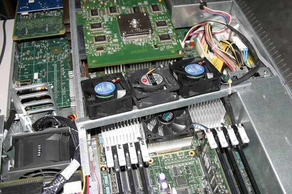
This Origin 350 graphics conversion used bplaa-yai's method of removing the processor shroud and installing three fans between the processor node and the VPro graphics board. This method only works with two-processor systems because the fans are positioned where the third and fourth processors would be in a four-processor system. If you have a four-processor Origin 350, or prefer not to remove the processor shroud from a two-processor system, an alternative method of adding VPro graphics is described here: viewtopic.php?f=14&t=16721099 (which is similar in concept to SGI's method of cooling a factory built Onyx InfinitePerformance). Neither method requires making an non-reversible changes to the base Origin 350.

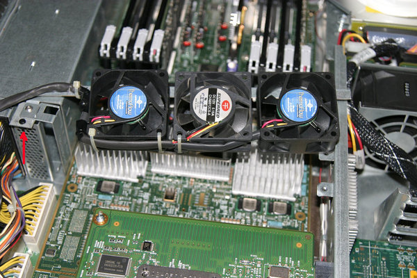
The fan support is a piece of heavy gauge sheet metal angle stock .5"x.5" wide by 10.25" long (the piece of sheet metal angle stock was selected because it closely matches the appearance of rest of the O350 chassis). It's supported on the PCI-side of the O350 by one of the threaded tabs used to secure the case lid, and by a fabricated tab on the power supply side (the tab was added so that the fan support would bisect the chassis at a right angle). The mounting tab on the power supply side is a simple 1" long x .5" wide section of heavy sheet stock with two drilled holes - one end is captured under the screw that closes the power supply cable clamp, the the other end extends outward to support the new fan bracket. The hole drilled hole in the other end of the tab was sized to fit a surplus fan push-pin mount (used to secure the newly added fan bracket to the tab), but a screw and nut would work equally well. To ensure that no contact occurred between the added fan bracket and the power supply cable bundle, the power supply was moved to the outside position (the O350 chassis has provisions for dual power supplies). O350's with a single power supply configuration normally have the power supply installed in the inside position (nearest the node board). In this instance the single power supply was moved to the outside position to ensure the added fan bracket wouldn't make contact with the power supply cable bundle. To prevent any issues with environmental checks done by the L1 controller, the power supply cable bundle was left attached to the same header on the system board (the power supply cable bundle attaches to the power supply with an edge-connector, so the cable bundle can be disconnected at the power supply end and moved there).

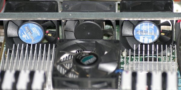
The two fans on the outside of the tree-fan array are two 60mm x 25mm Vantec TF6025 Thermoflow temperature controlled fans. These run at between 1900-4200 RPM, 9.9-24.2 CFM and 19-33.5 decibels, and were selected to provide reasonable cooling with minimal additional noise The center fan of the tree-fan array is a 60mm x20mm SuperRed CHA6012CS-A that's rated at 3900 RPM, 19.4 CFM and 29 decibels. The tach wire on the SuperRed is the only one of the three that's wired to the tach pin on the O350 fan connector. The SuperRed was selected because of its static 3900 RPM speed rating. The L1 in the O350 will trigger a (non-fatal) fan warning if the fan attached the the three-pin graphics fan header (located on the system board) drops below 1679 RPM. During a cold start the L1 environmental controller lowers the fan speeds by a percentage of the overall speed rather than to a specific RPM level. That percentage of the 1900 RPM start up speed of the Vantec fans isn't high enough to avoid triggering the warning, so the trick is to select fans that have a speed rating high enough to meet that they'll be above the L1 graphics fan warning level (1679 RPM). The the start up percentage of the fixed 3900 RPM speed of the SuperRed fan is around 1800 RPM (enough to avoid the 1679 RPM L1 fan warning), and even after hours of constant use hasn't exceeded 2200 RPM. At those RPM levels the SuperRed fan isn't noticeable over the original equipment power supply fan or radial exhaust fans, so as an alternative, three SuperRed CHA0612CS-A fans (or a similar fixed speed fan) could be used in all three positions with out adding to the O350's noise footprint.

Regardless of the fans (or cooling method) selected, particular attention should be paid to the fan connection pin-out. The fan header on the O350 system board uses a non-standard pin-out: Pin 1 - 12VDC; Pin 2 - Tach; Pin 3 - Ground (the location of pin 1 is screened on the system board). A 4-pin PWM fan may also be used; the O350 fan header and the PWM fan socket are keyed to allow connection of only the 3 necessary fan wires (although the 12VDC, tach and ground wires should be configured to match the O350 pin-out).

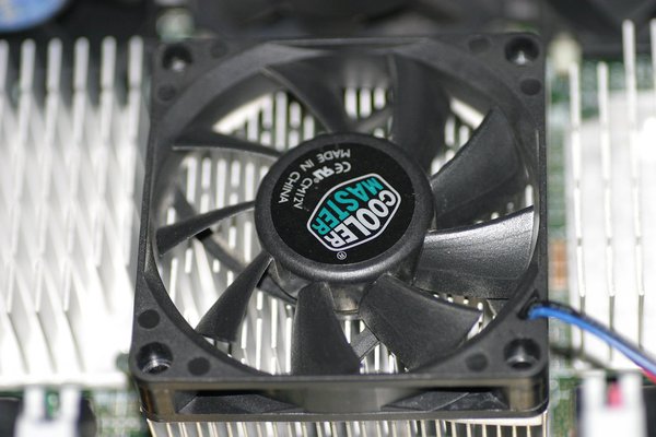
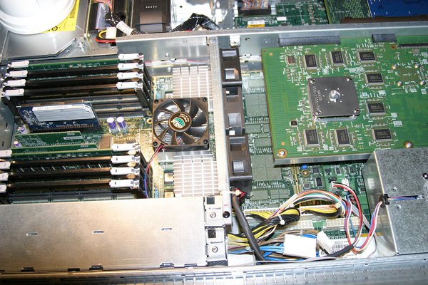
Because the Bedrock ASIC is usually shows up in an L1 'env' query as the hottest part of the system, a low-profile variable-speed thermally-controlled 70mm CPU cooler was added to the top of the Bedrock heat sink (70mm is a perfect fit). The cooler is secured by double-sided foam tape placed between the fan frame and hub and the heatsink. This lowered the Bedrock temperature an average of 8C, and the fan wasn't acoustically noticeable in the running O350.

There's been a few questions in the past concerning support for the VPro PCB. Fuel VPro boards come with a sheet metal support rail screwed to the edge of the board directly opposite of the XIO2 edge connectors. As it comes out of the Fuel that support rail is longer than the VPro PCB by several inches, and as a result would protrude into one of the added cooling fans. The one in the photo has been trimmed so that it was the same overall length as the VPro PCB (using a cut-off wheel, but a hacksaw or even tip-snips would do the job).
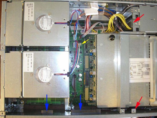
Before.jpg
The Origin 350 before modifications. The XIO-2 edge connectors for the VPro graphics board are marked with blue arrows, their position necessitates removal of the radial exhaust fan (just under the tail of the left-most blue arrow). The red arrows indicate the mounting points for the fan bracket that will be added to provide cooling for the processors, Bedrock ASIC and VPro. The metal processor shroud (under the tail of the lower red arrow) will be removed to provide clearance for the heatsink on the VPro board. The yellow arrow points out the location of the unused (until now) 3-pin fan header that controls the graphics board cooling fan. The O350 fan header uses a non-standard pin-out: Pin 1 - 12VDC; Pin 2 - Tach; Pin 3 - Ground. NOTE: A 4-pin PWM fan may also be used; the O350 fan header and the PWM fan socket are keyed to allow connection of only the 3 necessary fan wires (although the 12VDC, tach and ground wires should be configured to match the SGI pinout).
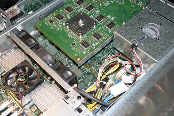
O350_V10-1.jpg
This system has a two-processor node board. The solder pads for processors three and four can be seen between the fans and the rear of the VPro board, and illustrate why this method wouldn't work with a four-processor node board - the fans are positioned where the third and fourth processors would be located.
O350_V10-2.jpg
The cooling array of three 60MM fans just behind the processor and Bedrock heatsinks; and a 70mm CPU cooler positioned on the heatsink of the Bedrock ASIC. The three-fan array pulls air across the heatsinks (away from the viewer); the fan on the Bedrock heatsink blows down.
O350_V10-3.jpg
A 70mm fan from a low-profile CPU Cooler was placed on the Bedrock heatsink (which is flanked by the processor heatsinks.
O350_V10-4.jpg
The Fuel VPro graphics board is located towards the top right of the photo. The Fuel version of the VPro board comes with a metal support rail that would extend into the area now occupied by the added cooling fans, so the rail was trimmed to be the same length as the VPro board.
O350_V10-5.jpg
Top view of the fan bracket. The right end was notched so that the bracket sat entirely on the added support tab (see the next photo) rather than on the power supply cable clamp.
O350_V10-6.jpg
Bottom view of the fans and bracket. The wiring was run across the bottom of the fans and cable-tied in place. The red arrow indicates the tab added under the power supply cable clamp (to support the fan bracket). The O350 chassis has provisions for dual power supplies. Single power supply configurations normally position the single power supply in the inside position (nearest the node board). In this instance the single power supply was moved to the outside position to ensure the added fan bracket wouldn't make contact with the power supply cable bundle. The power supply cable bundle was left attached to the same header on the system board.
***********************************************************************
Welcome to ARMLand - 0/0x0d00
running...(sherwood-root 0607201829)
* InfiniteReality/Reality Software, IRIX 6.5 Release *
***********************************************************************
Your solution is definitely a lot cleaner than mine - to put it lightly. My V10 may or may not be secured to the top of my O350's chassis by a piece of cardboard from a box of dish detergent over the matching screw hole... and my fans are secured by gravity and crossed fingers.

Mysteriously I've never had a single issue, even when running my system for 48+ hours at decent load, so I guess the ghetto engineering gods smiled on me.

fu wrote: reminds me of a graphics(?) board with hawaiian words i saw here some days ago.


That's an XTown - used to connect LEGO (Origin/Onyx2xxx) to a G-Brick for IR graphics. They say "The Best Pictures in the World" on them in Hawiian, because they were used to connect to "KONA" (the codename for Infinite Reality).

I miss the days of exciting stencils on SGI boards - once they got to the O350 the fun seems to have gone away.