Hardware Wanted

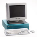
Ultra 64 dev board

I know that the chances of me finding someone who is willing to part with their beloved Ultra 64 board range from absolutely slim to completely and utterly none but I figured if I didn't ask then I'd have even less of a chance than I would if I did ask!

So there it is, I'm not expecting any replies to this request as I know for a fact that if I owned an Ultra 64 board then I'd never sell it either.

Oh well, thanks for looking (and probably laughing at me at the same time!)

I've got cash waiting in the slimmest of hopes that someone actually does want to part with their most prized possession. Obviously that figure will increase dramatically if it comes with the even rarer joybus connector board.

Cheers

Be patient.

I was in the same case. The U64 was a graal for me, I'm a big fan of N64 dev things and SGI.... 6 years with maybe 2 or 3 opportunity at high price... but two month ago a Sunday morning I finally found the graal on ebay for 49dollars (buy it now), without the joyboard.... I was just blown away and unable to wait the carrier for the delivery of the card, but everything come and it work now on my R4400/175Mhz indy with Irix 5.3.

I can only wish you a good and lucky hunt.
:PI: :PI: :PI: :Indigo: :Indigo: :Indigo: :Indy: :Indy: :Indy: :Indy: :Indy: :Indy: :Indigo2: :Indigo2IMP: :Octane: :O2: :O2: :1600SW: :Fuel: :PrismDT:
Wow, my heart skipped a beat then when I checked my email and saw that there had been a reply to this thread! I thought, for just one crazy moment, that someone was actually going to offer me a board to buy! How foolish am I!?

Patience is thankfully one thing I have in abundance, and I know that I'm going to need it for this one. You got insanely lucky getting an Ultra 64 for $49, I'd happily pay 10 times that amount for a known working version 2 board and even more with the elusive joybus board (as the Ultra 64 board really isn't that much use without the joybus board as you can't control anything you create and upload to it!). I, like you, am a huge N64 fan, have been ever since I saw Mario 64 in the flesh for the first time. I already have a fully working SN Systems SN64 dev kit for my N64 and as great as that is it still isn't an Ultra 64. There's something very romantic about creating demos on a board which is, to all intents and purposes, really just the guts of an N64 without the plastic casing, sitting prettily inside an Indy. I know I'll own one one day and it'll be a magically feeling to create my first working demo on something so close to the heart of the N64.
:D

I have expected that you will be very stressfull before you see my answser :D

I'm trying to launch the maximum of things on the board, but I have some trouble with compilation on some demos that were inside the SDK. In addition, without the joybus board, you can't clearly get everything of it. I have just prepared a basic indy with 5.3 and IDO before installing the OS2.0K, just to test the card. SDK documention is so crazy that I certainly need a lot of time ot investigate all files and README to find every bit of story about this board.

Thanks to an old post on the Neko forum for some command lines about Ultra64 board....

But your right, this Ultra board is very special, especially to have a thing that was not labelled Nintendo64 but Ultra64, a 1995 piece of history. Good job for the SN devkit :D . I have a 75% complete Partner Kit with an early ALPS 64DD dev drive (missing ISA / PCI board), but the ultra board is clearly easier to get working for a SGI fanatic.
:PI: :PI: :PI: :Indigo: :Indigo: :Indigo: :Indy: :Indy: :Indy: :Indy: :Indy: :Indy: :Indigo2: :Indigo2IMP: :Octane: :O2: :O2: :1600SW: :Fuel: :PrismDT:
It must be horrible to have the U64 board without the joybus board! The lack of it reduces the U64 to running non-interactive games/demos only. I'm unsure whether the PCB for the joybus board is multi-layer or not. If it is then it makes reproducing it a lot harder, if it's only single layer then it may be possible to copy it, the connectors could be salvaged from a dead N64. I've only seen a few pics of it on the net and from those it doesn't look too complex but obviously it's not possible to tell if it's a multi-layer PCB or not. It has the 4kb EEPROM onboard for game saves, which apparently can be upgraded to the 16kb one.

I can compile most of the SDK samples and run/debug them on my SN64 but obviously that's all done on a PC host using the SN Systems supplied compilers/linkers/etc, the resulting binary is then sent down the SCSI cable to the SN64. Some of the SDK samples rely on the host/target communication mechanism of the Indy/U64 combination and they are never going to work on my dev kit without a major rewrite. But at the end of the day, as much fun as the SN64 kit is, it just isn't quite the same feeling developing N64 demos on a relatively up-to-date PC as it would be doing all that on an SGI machine. Call me nostalgic but hey that's just the way I see it!

The search continues.......
The Joybus board is likely 4 layer, but that's probably for EMC, not due to the complexity. I'm certain that all the Nintendo-specific ICs are also found either in the controllers or on cartridges (BU9850 e.g. on Super Mario 64). I actually wanted to have mine x-rayed to help in reverse-engineering it, but I missed the opportunity to have that done. If anyone wants to spend an afternoon at my desk probing my joyboard, you're welcome to visit me near Cologne.

Image
Image
Image
Image
Image
WOW! Excuse me whilst I wipe the drool from my chin! The holy grail of all N64 dev items!

Thank you so much for those high res pics and for your comments. I've never before seen such detailed pics of the Joybus board before. It doesn't look overly complex from a component view (7 caps, 12 filter caps, 9 resistors, 2 diodes, all SMT) and an electrolytic cap. Then there's a 30 way connector for the 5 RJ11 cables to the U64 board and the two N64 controller connectors. The BU9850 is the 4k EEPROM which could always be salvaged from an unwanted N64 cart. That just leaves the PCB itself and the two ICs which I can't make out the markings on (U1 and U2), I presume they're SSI/MSI glue logic of some kind. Is it possible you could identify those two for me please, if the markings are legible.

If I'm ever lucky enough to be able to secure an Ultra 64 board and it comes without a Joybus board (which is the most likely scenario as these things are rarer than hens teeth) then I'd be very interested in starting the process of making a copy of your Joybus board at some point. I have no experience whatsoever in doing this kind of thing so if anybody reading this knows whether it is possible or not then please speak up.

btw I'm curious as to the origin of the 7 hand soldered wires on the underneath of your U64 board. I presume it came to you like that. Do you have any knowledge of what their purpose is? Looks like they go from the Joybus connector ports to various SMT components. I wonder if all U64 v2.0 boards needed this fix or whether it was just your board.

Many thanks once again for your help and info.

Cheers
My Ultra64 has never been used, it's still as it came from SGI - I think those wire wrap fixes can be seen on other examples as well, so they may be standard for 2.0 boards.

reverse-engineering such a board isn't easy, but entirely possible.

Here's a photo instead of the scans of the joybos board, with light at an angle, the inscriptions on U1 + U2 are actually readable. I think U2 is the same as U8 in a real N64, I don't see any equivalent for U1. The FIL coils(?) should be recyclable as well as some of the caps since they should be basically equivalent on the joybus board and the Ultra64.

You can use geda-gaf and PCB, conveniently provided in nekoware (possibly beta) to design your replacement board.
Image
Thanks for the extra pic. Looks like U2 is a quad buffer/line driver (74LVC125A). There's not a lot to go on as regards U1 but judging from its '425' marking it potentially could be a 74LVC425A (voltage translator to translate between TTL and CMOS voltage levels) although there's very little info on the net about said IC. Looks like 4 of the inputs to U1 come from the 30 pin connector that goes to the host Indy but without a data sheet for that chip there's a lot of guess work going on! I've never measured the voltages used in a real N64 controller so I don't know whether they're CMOS levels or TTL levels. I've also never designed a PCB before and wouldn't know where to start unfortunately so I'd have to commission someone to do the work for me if it came to that. All this is moot of course until I can actually lay my hands on a U64 board.

If you don't mind me asking, how on earth did you manage to acquire an unused Ultra 64 board??? Or shouldn't I ask?

Thanks
Actually the Joyboard is not the only option to use the Ultra64 board.
Nintendo also manufactured some N64 controllers that could be plugged directly to the Ultra64 board without having the Joyboard; these are also rare but when found are generally less expensive than the Joyboard...
The Joyboard is essential only to develop/test software that uses the EEPROM used to save game data.
That would mean that the JoybusBoard should more or less directly patch through the Joypad data lines to the RJ plugs, and therefore one should be able to just cut off the N64 plug of a Joypad and crimp on an RJ connector. That should be good news for anyone who's looking for a Joyboard.

It turns out that that is indeed the case. Pin 1 + 4 of both "left" and "right" Socket pairs are all connected together and lead to pins 2, 8, 14, 20, 26 on the ribbon cable connector. Pin 2 of "left" is connected to 6, 3 to 10. Pins 1-6 on the ribbon cable connector go straight to 1-6 on an RJ12,7-12 connect to the next RJ12 etc. That's an "interesting" choice, because JP1 needs to be connected to both the first and second RJ12 connector, and JP2 connects to both the second and third.

Code: Select all

JP1
1  2,8,14,20,26
2  6
3  10
JP2
4  2,8,...
5  12
6  16
JP3
1  ...
2 18
3 22
JP4
4  ...
5  24
6  28
I wasn't aware that Nintendo ever made controllers that plugged directly into the U64 board so thanks for that jollyroger. I don't suppose you happen to have one of these fabled controllers do you, or at least a pic of one as I've had no joy finding a pic of one on the net? I wonder if there's any inline circuitry in the cable of this special controller itself which does some translation between controller and U64 or whether it's simply a standard N64 controller with an RJ11 plug at the end instead of the usual N64 plug. I agree with caravan though this could potentially be very good news for U64 owners who don't have the joybus board. The N64 controller only uses 3 wires for its connection to the N64 unit so it could just be a case of identifying the 3 wires involved from the joybus board and crimping an RJ11 onto the end of the N64 controller cable with the wires in the correct positions.
Curiosity.

Are you going to develop N64 games? Or is this just for serious fun?
:Onyx2:
Just from visually tracing Canavan's pictures, it's clear that the 5 RJ-11 plugs on the board correspond to the four controllers and the memory unit. Each controller has a 3-pin socket, with power and ground on the outer pins and data on the center pin. the power and grounds are all the same (though they have individual ferrite protection)
each RJ-11 cord has the same pinout, with pin 2 for power and 4,5 for ground (seen from the joybus board). Whereas the controllers have 1 data pin, the RJ-11 plugs on the U64 have 3 data pins (probably send and receive plus a clock). Besides the memory unit, the joybus board clearly does buffering, 1-wire encoding/decoding, and diode protection. So what I expect is that the "controllers for U64 dev board" are different from consumer controllers by bringing the send,receive,and clock signals out directly without 1-wire encoding, i.e. they are simpler than the consumer controllers by missing that component.
:PI: :O2: :Indigo2IMP: :Indigo2IMP:
Thanks for the input robespierre. So based on your musings don't you think it would be possible to use retail N64 controllers on the U64 board by simply changing the cable plug for an RJ11?

@mia - Yes, I do intend on using the U64 board (if and when I ever get hold of one!) for developing N64 games, mainly 2D platform games. That's what I currently do with my SN64 dev kit but I'd prefer to develop on an Indy/U64 combination for personal reasons.
cmonkey wrote: @mia - Yes, I do intend on using the U64 board (if and when I ever get hold of one!) for developing N64 games, mainly 2D platform games. That's what I currently do with my SN64 dev kit but I'd prefer to develop on an Indy/U64 combination for personal reasons.


Way cool, you should blog that. Even if I have no interest in gaming or N64 stuff, I think this is great.
Was the SDK easy to retrieve, after so many years?
:Onyx2:
cmonkey wrote: Thanks for the input robespierre. So based on your musings don't you think it would be possible to use retail N64 controllers on the U64 board by simply changing the cable plug for an RJ11?


I think they could be adapted by soldering RJ11 cables onto the right internal points, as long as the cable is kept relatively short. There could be other changes to the special controllers. No way to know until you try it, of course.
:PI: :O2: :Indigo2IMP: :Indigo2IMP:
You shouldn't solder but crimp new plugs (note the plural) onto the gamepad cable after cutting off the old connector. . Re-read my last post on the previous page for the pinout, be sure to compare the pin numbers given with the photos I've posted. The only components on the Joyboard in the signal path are the FILT-inductivities. Since those are not duplicated on the Ultra64 board, you may want to add something equivalent to a modified Gamepad it the N64 has them as well.
So what I expect is that the "controllers for U64 dev board" are different from consumer controllers by bringing the send,receive,and clock signals out directly without 1-wire encoding, i.e. they are simpler than the consumer controllers by missing that component.

No, they should be the same, except maybe for some passive filtering stuff on the cable and the different plug.

I only see diodes D1 + D2 on the Joybus Board, I'd be surprised if they had anything to do with the 4 Joypad ports.